Turbo machine and method for the operation thereof

Inactive Publication Date: 2015-11-12
SIEMENS AG
View PDF3 Cites 0 Cited by
  • Summary
  • Abstract
  • Description
  • Claims
  • Application Information

AI Technical Summary

Benefits of technology

The invention is a seal gas preparation module that includes a control valve for controlling the pressure and flow of seal gas. The module is designed to handle high compressor pressures, reducing the need for expensive components. This design also reduces the risk of ignition or contamination, resulting in lower costs and improved safety. Overall, the invention provides a more cost-effective and safer way to prepare seal gas.

Problems solved by technology

In the case of very high-pressure compressors with dry gas seals, it is difficult to acquire components for the function preparation (liquid separation, filtering, heating, pressure control).
Furthermore, these components are very expensive.

Method used


Image

  • Turbo machine and method for the operation thereof
  • Turbo machine and method for the operation thereof

Examples


Embodiment Construction

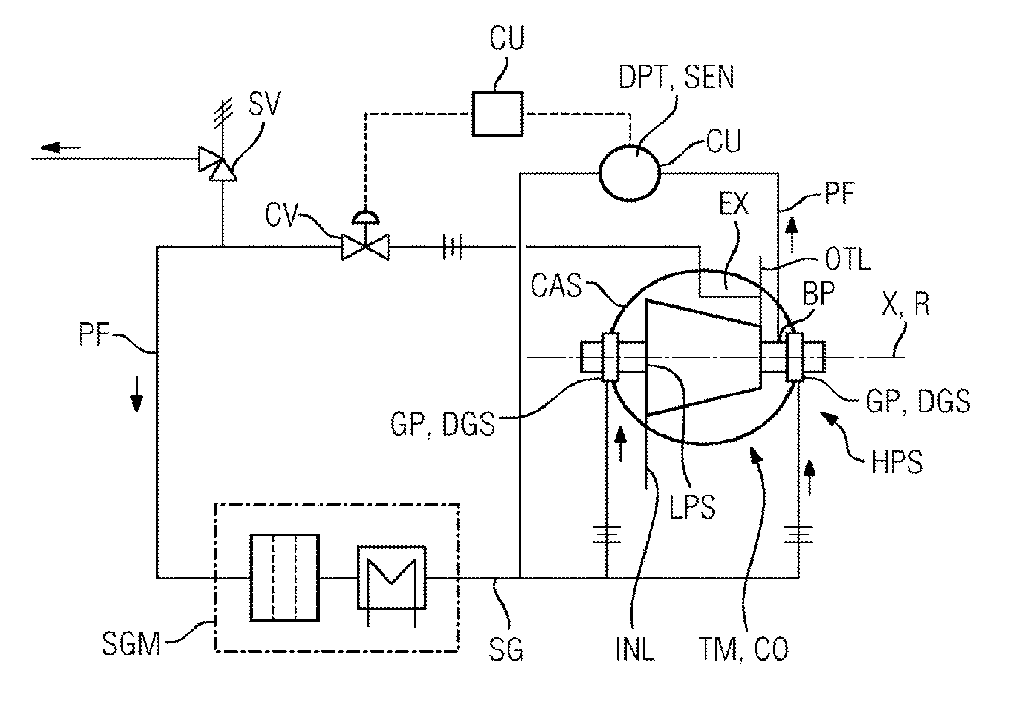
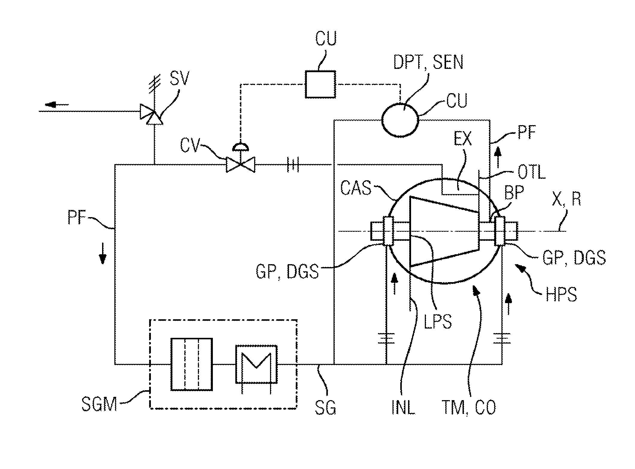
[0013]FIG. 1 shows a schematic representation of the turbomachine TM or method according to embodiments of the invention as a flow diagram. The turbomachine TM in the exemplary embodiment is designed as a turbocompressor CO with a rotor R which extends along an axis X. Along the axis X, the turbocompressor CO has a high-pressure position HPS and a low-pressure position LPS at which, during operation, a process fluid PF in the flow path of the turbomachine TM is, respectively, at a higher or a lower pressure. A gap GP (not shown in more detail) between the stator CAS and the rotor R of the turbomachine TM is sealed on both sides of the turbomachine by means of gas seals DGS. The turbomachine TM, or the stator CAS which is formed as a casing, has an inlet INL and an outlet OTL, wherein a process fluid PF enters the turbomachine for compression through the inlet INL and is conveyed to the outlet OTL where it leaves the turbomachine at a higher pressure. An extraction point EX for the p...


PUM


Abstract

A turbo machine, particularly a turbo compressor, including at least one rotor, which extends along an axis, at least one gas seal, which uses a seal gas to seal a gap between the rotor and a stator of the turbo machine, and a processing module, which processes process fluid taken from the high-pressure position at a tapping into seal gas, which seal gas is fed to the gas seal is provided. To reduce the investment costs for processing the seal gas for the gas seal, a control valve is provided in a first pipe of the turbo machine, the turbo machine has a control unit and a sensor in a second pipe for the seal gas between the processing module and the gas seal, and the control unit is designed such that the control valve controls the pressure or the mass flow or the volume flow measured by the sensor.

Description

CROSS-REFERENCE TO RELATED APPLICATIONS[0001]This application claims priority to PCT Application No. PCT / EP2013 / 065685, having a filing date of Jul. 25, 2013, based on DE 102012215823.5 having a filing date of Sep. 6, 2012, the entire contents of which are hereby incorporated by reference.FIELD OF TECHNOLOGY[0002]The following relates to a turbomachine, in particular a turbocompressor, comprising at least one rotor which extends along an axis, comprising at least one axial high-pressure position, at least one axial low-pressure position, wherein, when the turbomachine is in operation, the pressure of a process fluid is higher at the high-pressure position than at the low-pressure position, at least one gas seal which seals, by means of seal gas, a gap between the rotor and a stator of the turbomachine, a preparation module which prepares process fluid, extracted from the high-pressure position at an extraction point, to give seal gas, which seal gas is supplied to the gas seal. The ...

Claims


Application Information

Patent Timeline
IPC IPC(8): F04D29/12F04D29/10F04D27/02
CPCF04D29/124F04D29/104F04D27/02
Inventor ALFES, LUDGER
Owner SIEMENS AG
Why Eureka
Try Eureka