Redox flow battery system and method of controlling it

a technology of redox flow and battery system, which is applied in the direction of fuel cell auxiliaries, fuel cell auxiliaries, electrochemical generators, etc., can solve problems such as major failures of the booster

Active Publication Date: 2015-11-12
HYDRAREDOX TECH HLDG
View PDF5 Cites 12 Cited by
  • Summary
  • Abstract
  • Description
  • Claims
  • Application Information

AI Technical Summary

Benefits of technology

[0037]The voltage differences measured between open circuit voltage (OCV) and the total cell voltage (TCV) measured at the connections to the DC rail provide a measure of the total effect of factors of irreversibility of the electrochemical processes taking place in each of the two electrolyte solutions, during a charge phase and during a discharge at a respective current load.
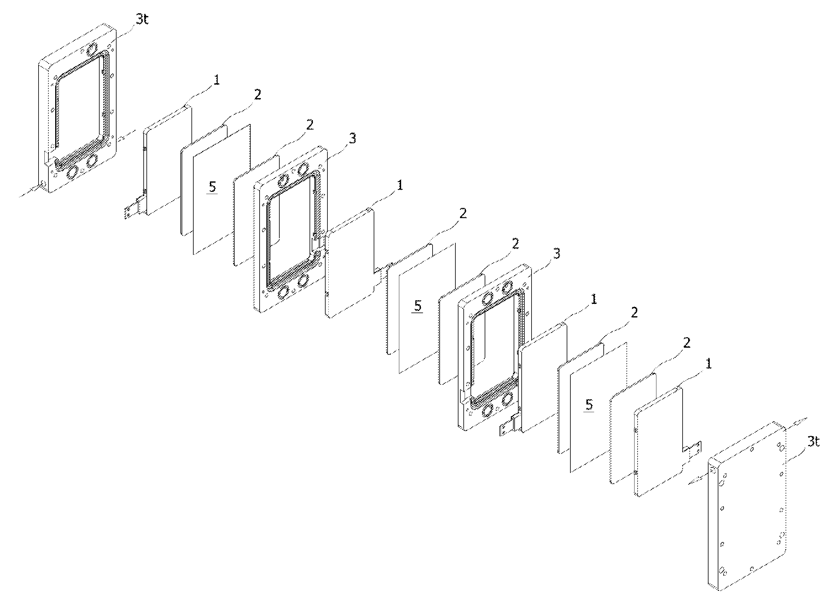
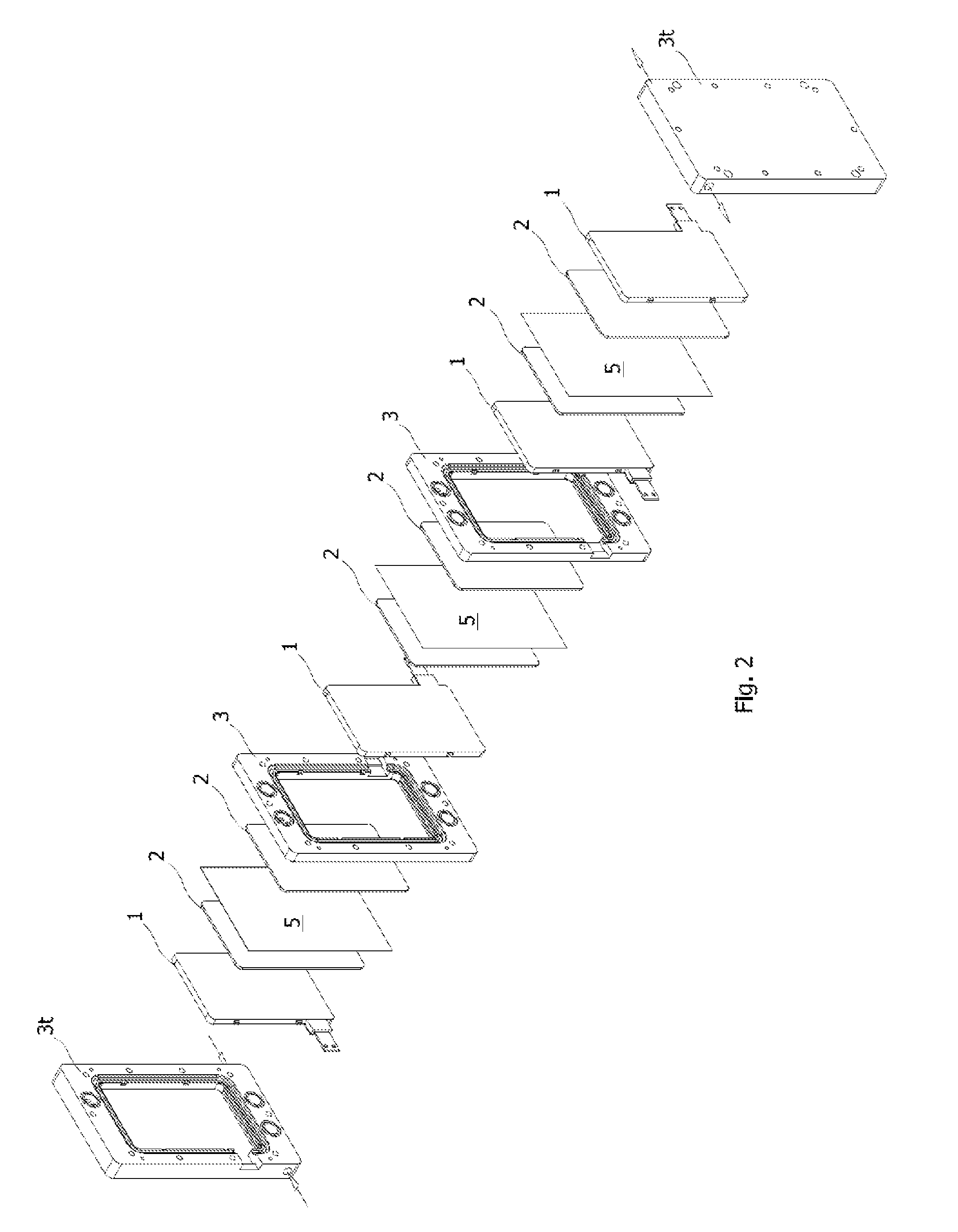
[0038]According to an enhanced monitoring embodiment, simple, externally deployed, current sensing means coupled to the electrical connection stem or lug of each back plate of current distribution to a respective felt electrode or electrodes, provide a measure of the current flowing through the single felt electrode or to the two felt electrodes coupled to the same back plate of every multi-electrode monopolar cell. Any discrepancy of the current flowing through any back plate of current distribution to the respective felt electrodes from the expected value, corresponding to the total current flowing through all the multi-electrode monopolar cell stacks in series, divided by the number of elementary cells (equivalent to the total number of back plates less one) and multiplied by two for the back plates interleaved to similar back plates of opposite sign, can be detected and monitored for eventually isolating the monopolar cell stack from the multi stack system and replacing it by enabling the operation of a stand-by spare monopolar cell stack.

Problems solved by technology

After a long experience of designing and testing redox flow battery systems, the applicants perceived that a notion derived from measurements of process parameters as done in known commercial systems, most of which provide a generally “averaged” value of the relevant parameter, of the would be conditions the electrochemical processes at the carbon felt electrodes of any specific cell of a battery stack take place may often be moot and as such to foster major failures.

Method used


Image

  • Redox flow battery system and method of controlling it
  • Redox flow battery system and method of controlling it
  • Redox flow battery system and method of controlling it

Examples


Embodiment Construction

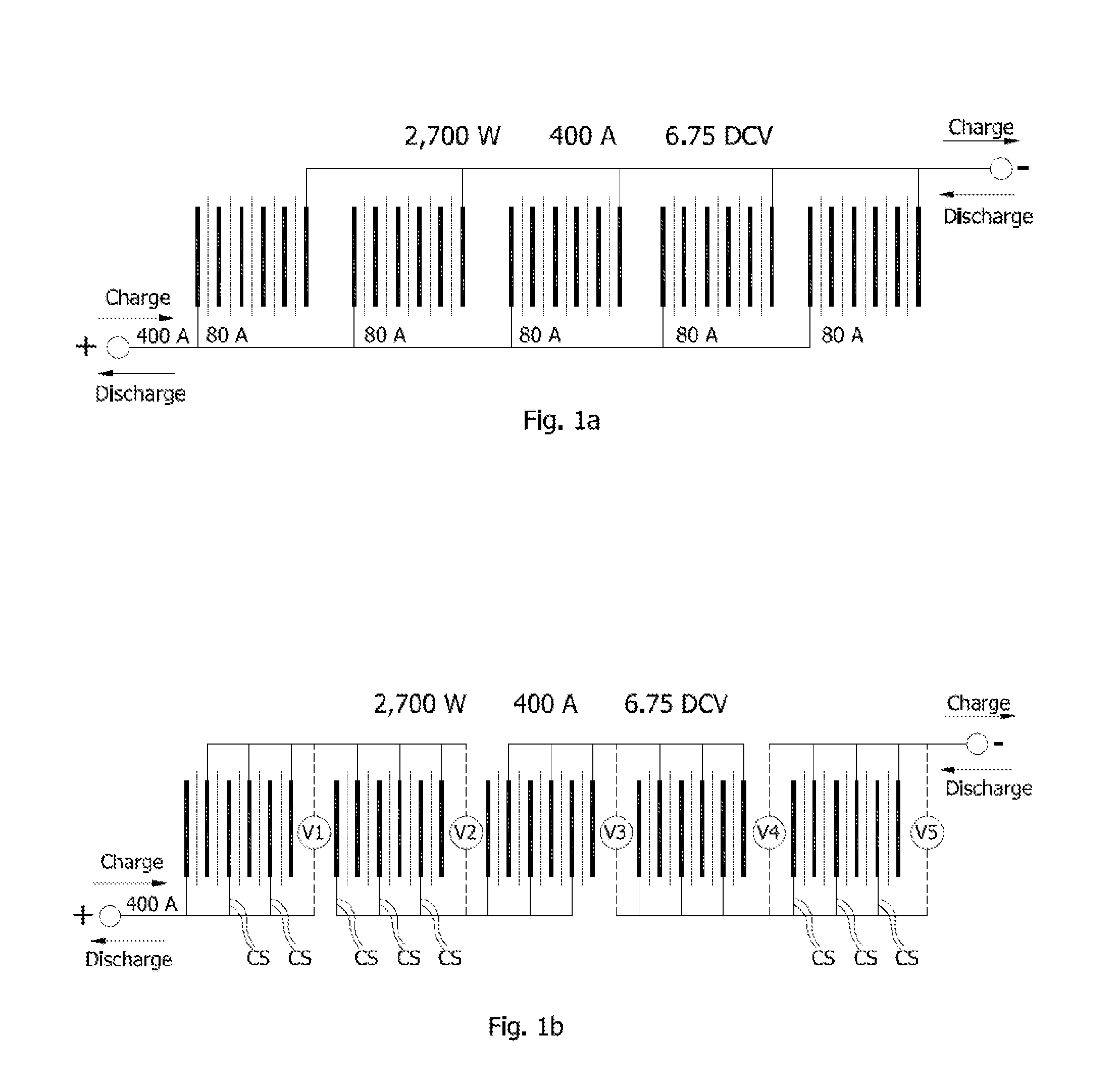
[0053]Differently from the substantial blindfoldness of the operator of a traditional bipolar cell stack plant configuration illustrated in FIG. 1A, in detecting in which of the five stacks any of the five bipolar cells in series may be malfunctioning with the risk of a destructive damage taking place and eventually leading to a plant downtime for carrying out investigations on each isolated stack, the multi monopolar cell stack architecture of this disclosure illustrated in FIG. 1B allows a truly in depth monitoring of the conditions of operation of the necessarily large number of stacks and of elementary cells a redox flow battery system requires.

[0054]FIG. 1B is an electrical scheme relative to a redox flow multi monopolar cell stack system of this disclosure that in a purely exemplary manner (with electrical ratings identical to those of the traditional configuration of FIG. 1A) comprises five distinct monopolar multi compartmented cell stacks, connected in series to a positive ...


PUM

PropertyMeasurementUnit
voltageaaaaaaaaaa
open circuit voltageaaaaaaaaaa
total cell voltageaaaaaaaaaa

Abstract

A novel multi cell stack architecture has specific features allowing deployment of simple electrical instrumentation of data collection/monitoring of crucial hydraulic, electrical and electrochemical quantities, on the basis of which the operator or electronic controller is able to gather/process critical information of such a depth and enhanced reliability, for immediately identifying any cell in “state of sufferance” and eventually to exclude it from the system and possibly substitute it with a spare cell. A method of monitoring/controlling the operation of an all-vanadium redox flow battery system is also disclosed.

Description

BACKGROUND OF THE DISCLOSURE[0001]1. Technical Field[0002]This disclosure relates to redox flow battery systems for energy storage employing multi-cell electrochemical reactors composed of sequences of “filter press” assembled planar elements to form a battery stack and a method of monitoring operating conditions and controlling the functioning of every electrode of the multi-cell stack.[0003]2. Description of Related Art[0004]Redox flow battery systems are increasingly attracting interest as efficient energy conversion systems. Among the numerous redox couple candidates, the all vanadium redox system being one of the most preferred.[0005]Structurally, the electrochemical reactors that have been proposed for redox flow battery systems, have been derived from the electrochemical reactor structures developed for general electrolysis processes, the only adaptation having concerned the materials employed as electrodes.[0006]The documents GB-A-2,030,349, U.S. Pat. No. 4,786,567, WO99 / 393...

Claims


Application Information

Patent Timeline
Patent Type & Authority Applications(United States)
IPC IPC(8): H01M8/18H01M8/04H01M8/20
CPCH01M8/188H01M8/20H01M8/04544H01M8/0438H01M8/04574H01M8/249H01M4/8615H01M4/96H01M8/0206H01M8/0213H01M8/0228H01M8/0273H01M8/0276H01M8/0297H01M8/04388H01M8/04395H01M8/04552H01M8/04671H01M8/04955H01M8/0278Y02E60/50H01M8/241H01M8/24
Inventor SPAZIANTE, PLACIDO MARIADICHAND, MICHAEL
Owner HYDRAREDOX TECH HLDG
Why Eureka
Try Eureka