
Heat transfer component with dendritic crystal structures and purpose and method of use for such a component

a technology of dendritic crystals and components, applied in the direction of cooling/ventilation/heating modifications, modifications by conduction heat transfer, semiconductor devices, etc., to achieve the effect of improving the efficiency of heat dissipation, facilitating dendritic crystal growth, and increasing the practical value of the present invention

Inactive Publication Date: 2015-11-12
FAR EAST UNIVERSITY
View PDF14 Cites 5 Cited by
  • Summary
  • Abstract
  • Description
  • Claims
  • Application Information

AI Technical Summary

Benefits of technology

The present invention offers a new perspective on dendritic crystals by using them in a heat transfer component to provide directional heat transfer and improving heat dissipation efficiency. The fractal structures on the dendritic crystals provide additional surface area for heat dissipation. The use of whiskers or cutting processing to produce crystal defects required for the growth of dendritic crystals allows for increased practical value and further enhances the heat dissipation efficiency of the dendritic crystals. The spacing between each dendritic crystal helps to prevent heat deposition and ensure the heat dissipation effect. Multiple dendritic crystals with a length of 1-5 mm and spacing of 0.1-5 mm exhibited optimal heat dissipation effect.

Problems solved by technology

Further, the aforementioned crystal defect is any one of or a combination of a whisker, protrusion, burr, and an edge.

Method used


Image

  • Heat transfer component with dendritic crystal structures and purpose and method of use for such a component
  • Heat transfer component with dendritic crystal structures and purpose and method of use for such a component
  • Heat transfer component with dendritic crystal structures and purpose and method of use for such a component

Examples


Embodiment Construction

[0052]Based on the technical characteristics described above, the embodiments of the primary effects of the present invention, that is, the purpose and method of using dendritic crystals for heat transfer, are described below.

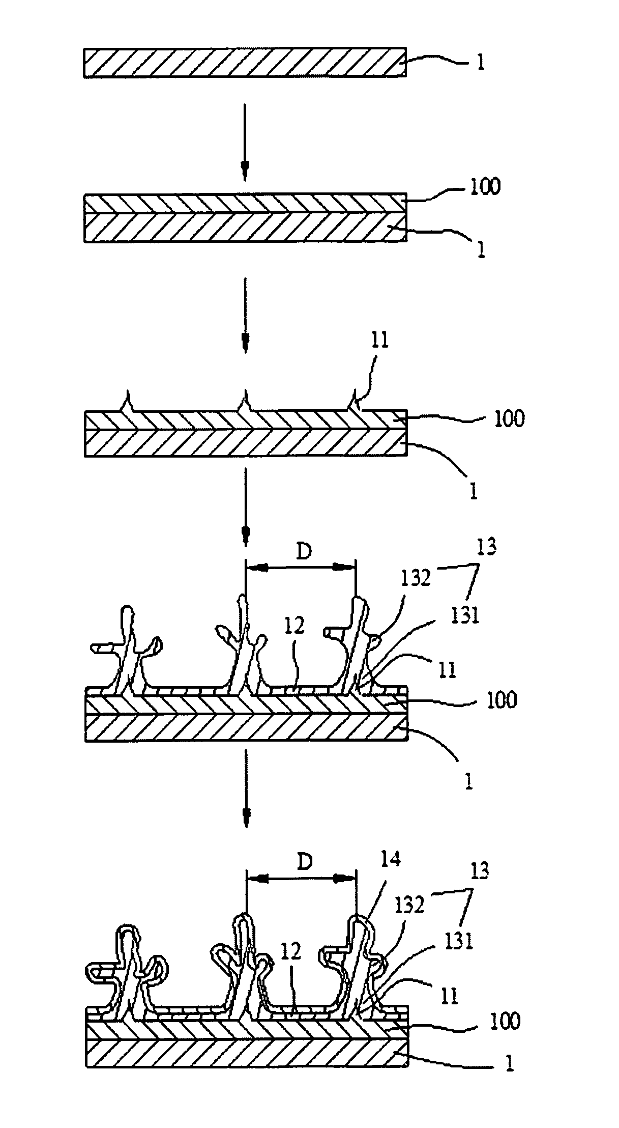
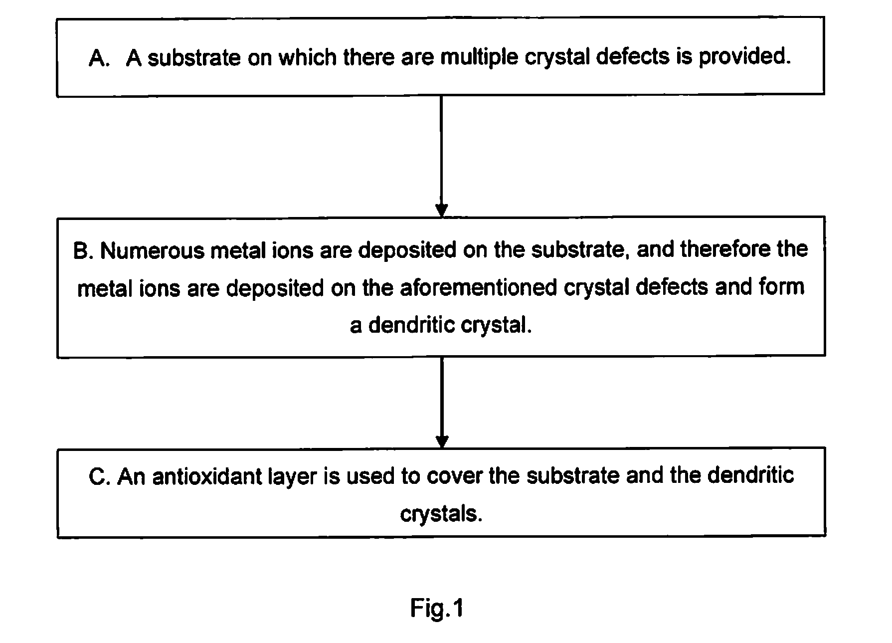
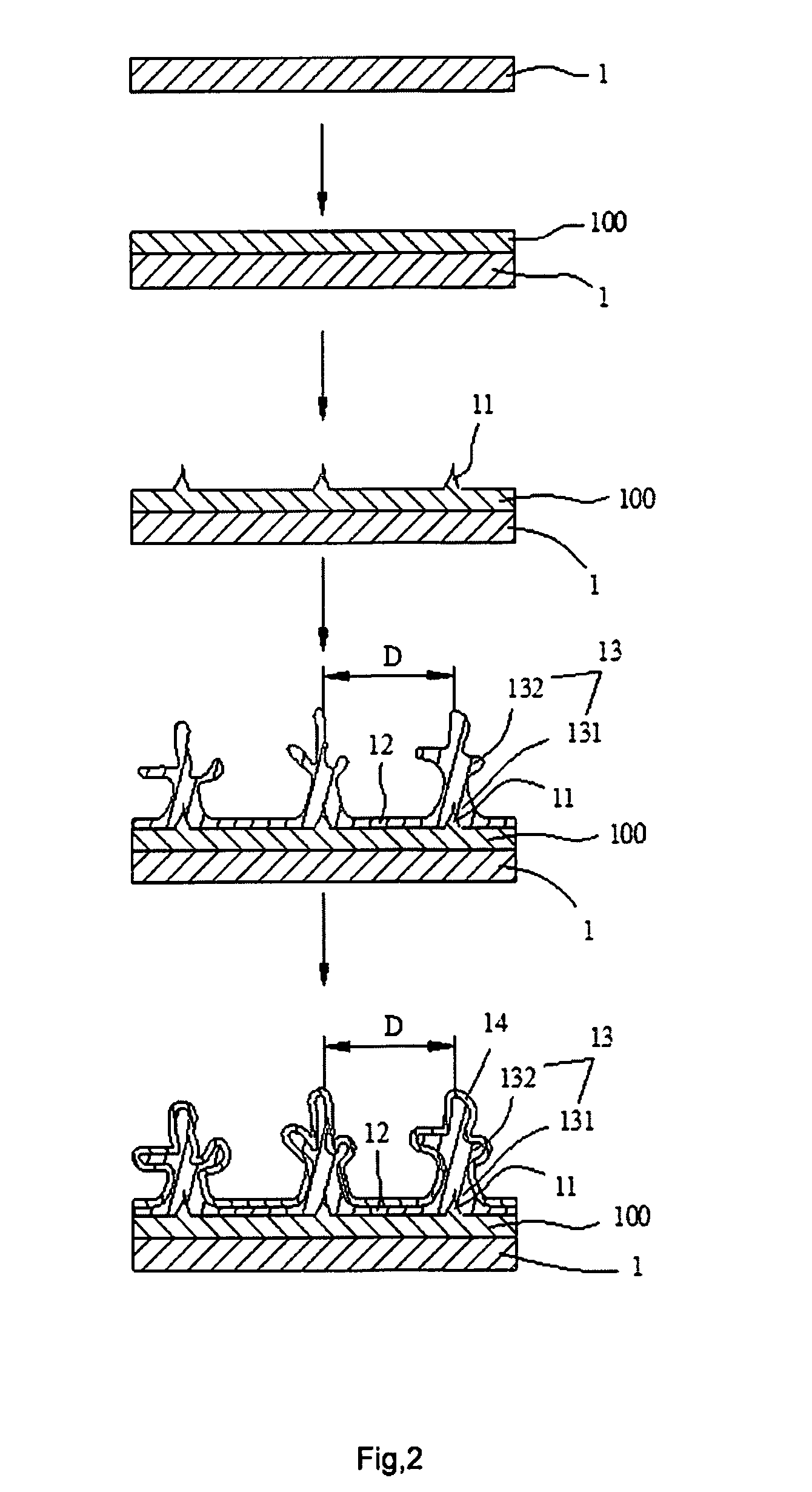
[0053]Referring to FIGS. 1 and 2, the embodiment of the dendritic crystal structures used for directional heat transfer, the flowchart of the preparation procedures, and the flowchart of the preparation process are revealed.

[0054]A. A substrate (1) is provided, and the substrate (1) contains multiple crystal defects (11). Crystal defect (11) in the present invention is defined as encompassing whiskers as well as point and line defects that exhibit crystal structures with destroyed regularity. The preferred substrate (1) is a metal (e.g., copper or aluminum) featuring high electrical conductivity and thermal conductivity. The substrate is preprocessed by using a degreasing procedure and a sensitization procedure, which entails immersing the substrate in acidic s...


PUM


Abstract

A heat transfer component with dendritic crystal structures and a purpose and method of use for such a component; this component is used to resolve the deficiency concerning conventional heat transfer components possessing inadequate surface areas for heat dissipation. Dendritic crystal structure is comprising: a substrate and multiple dendritic crystals. The substrate contains multiple preset crystal defects in which all the dendritic crystals deposit and congregate, and a space is located between each dendritic crystal for thermal convection. Regarding the method of use, the substrate is connected to a heat source, which then induces directional heat transfer from the substrate and the metal layer to the main branch and at least one sub-branch of the dendritic crystal, or the dendritic crystal is placed on a heat source, which induces heat transfer from the crystal to the substrate.

Description

BACKGROUND OF THE INVENTION[0001]1. Field of the Invention[0002]The present invention relates to a heat transfer component with dendritic crystal structures and its purpose and method of use; in particular, using dendritic crystals formed through metal ion deposition as a heat transfer component. The dendritic crystals differ from the whiskers that grow from metal because of internal stress.[0003]2. Description of the Related Art[0004]Lightweight and thin electronic devices are growing in popularity; thus, relevant industrial operators have endeavored to devise a method of rapidly and effectively cooling electronic devices using small heat transfer components.[0005]Commonly used heat transfer components are composed of copper or aluminum metal substrate that has excellent thermal conductivity. In addition, a heat sink is placed on the substrate to dissipate the heat generated by the cooling electronic device into the surrounding environment. However, the surface area on the heat sin...

Claims


Application Information

Patent Timeline
Patent Type & Authority Applications(United States)
IPC IPC(8): H05K7/20
CPCH05K7/20509H01L23/367H01L23/3736H01L2924/0002H01L2924/00
Inventor WANG, JENN-SHINGWANG, YU-CHINGWU, JIA-YU
Owner FAR EAST UNIVERSITY
Learn More