Mesh Network System and Techniques

Active Publication Date: 2015-11-26
SMARTREK TECH
View PDF24 Cites 55 Cited by
  • Summary
  • Abstract
  • Description
  • Claims
  • Application Information

AI Technical Summary

Benefits of technology

[0018]It is an object of the present to provide a reliable, fast and low power consumption remote data acquisition and device control with multiple channel-sharing clients in an environment with multiple interference-generating physical elements,

Problems solved by technology

Clock synchronization is a known problem for distributed radio transceiver networks.
Thus, in order to accommodate low effective duty cycles, one has to typically use higher-cost crystals, a combination of multiple crystals.
This also limits the hardware platforms onto which a cooperative bit-synchronized mesh network can be deployed, and legacy retrofitting is usually impossible, and design required dedicated hardware platforms, lest one needs to cope with less efficient minimum network power consumption, a trade-off that can be unacceptable for long-range, high RF power, long-lasting, low power consumption applications, such as in high-interference locations such as large forest deployments.
The alternate method for network-wide clock synchronization is using out-band methods in order to avoid the clock tolerance problem, such as using GPS time base from a GPS unit installed per-node, with implied hefty penalties in node cost, due to raw hardware cost as well as increased integration complexity.
A supplementary technical challenge when employing cooperative bit-synchronized networks is that timing is key, and thus, for single core processors employed as mesh controllers, all interrupts must be typically be deactivated before a timing-critical operation (such as a packet transmit begin trigger signal) occurs.
In other terms, running

Method used


Image

  • Mesh Network System and Techniques
  • Mesh Network System and Techniques
  • Mesh Network System and Techniques

Examples


Example

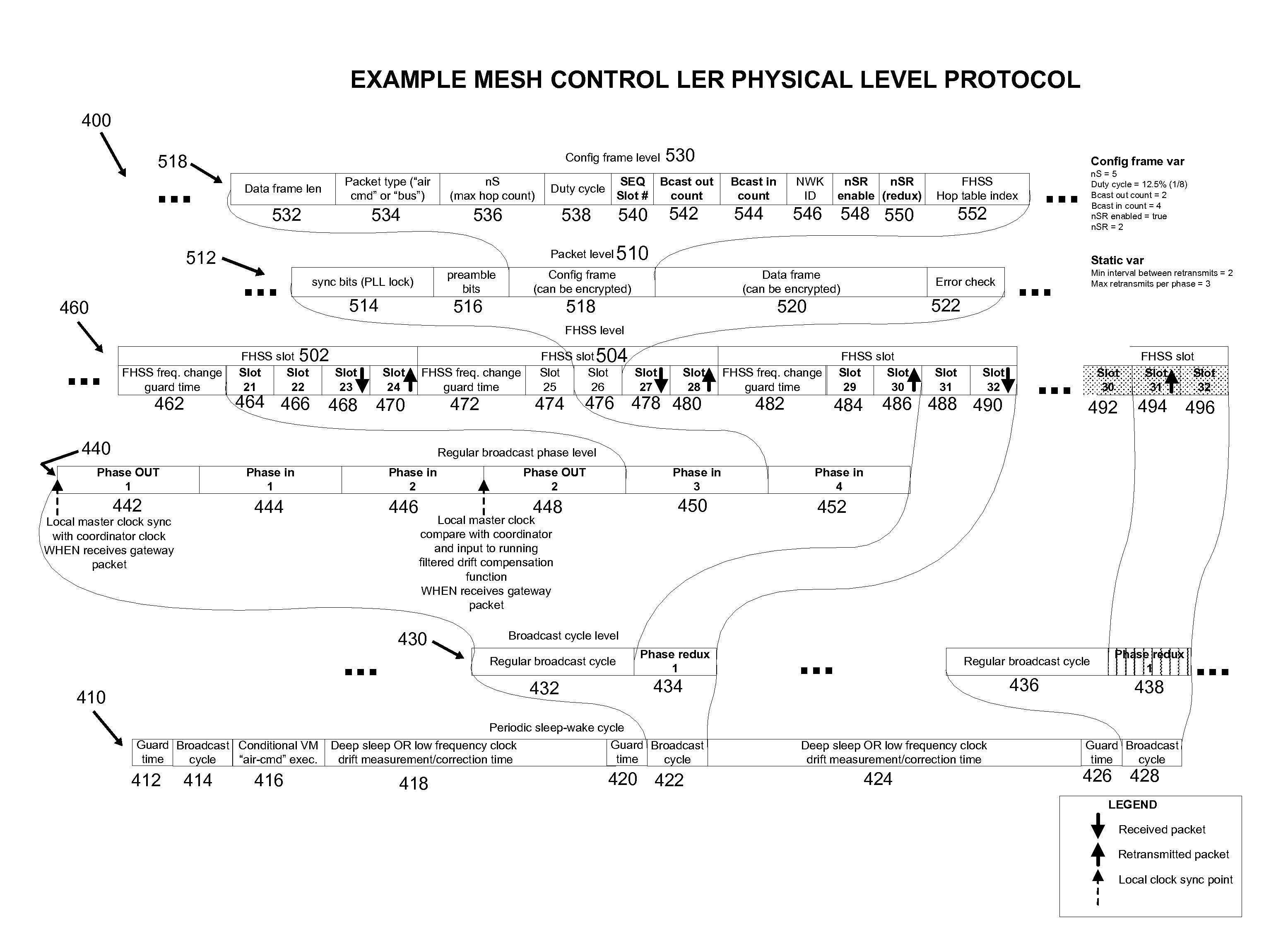
[0076]Broadly, in accordance with an embodiment, there is provided a novel application of a bit-synchronized mesh network leveraging the lower theoretical time bound of a mesh network packet broadcast which is not limited by conventional contention effects due to antenna diversity phenomena, as well as leveraging the capture effect inherent of FM radio distributed networks as a fallback transmission method in the case of heavy multi-path, delay-induced and physical occlusion-caused interferences, in order to not only enable a standard master-slave round-robin sensor polling scheme as seen in most distributed sensor networks, but also to enable multiple bandwidth-asymmetric clients that can replicate the data received by said master at no supplementary network bandwidth or speed cost, and thus allows more leeway as for the choice in the optimal power source for each node in terms of cost and maintenance requirements. In addition, standard flooding scheme is hybridized with a slow-flo...


PUM


Abstract

The present relates to a node to be integrated in a network of wirelessly connected nodes, to a network system, to method for operating a node of a network, and to a method for communicating within a network. A method is disclosed for communicating within a network of cooperatively synchronized nodes, configured to broadcast data packets to the network during broadcast phases through a flooding mechanism, each data packet comprising hop data. The method comprises, for each broadcast phase, broadcasting a data packet from a source node during a predetermined time slot; and receiving the data packet at one or more destination node during said predetermined time slot. The broadcasting and receiving are repeated according to the hop data, at respective predetermined time slots, wherein each destination node corresponds to a source node in a next execution of broadcasting and the data packet received corresponds substantially to the data packet to be broadcasted in the next repetition.

Description

FIELD[0001]The present relates to network systems and techniques, and more particularly, to a node to be integrated in a network of wirelessly connected nodes, to a network system, to method for operating a node of a network, and to a method for communicating within a network.BACKGROUND[0002]The cooperative synchronized networks idea stems from the principle of having a synchronization on the physical layer of a given mesh network, be it via wavelength-level phase synchronization, or via a more easily achievable implementation with synchronization at bit-level in order to enable deployment on existing industry-standard design targets.[0003]Known in the art are contention-enabled technologies such as Zigbee™, for example.[0004]Bit-synchronized networks are a special case of antenna diversity found in phased array radar, for example, with less timing constraint, which is enough for ensuring minimal interference between simultaneous packet transmission of multiple node neighbours, the ...

Claims


Application Information

Patent Timeline
IPC IPC(8): H04W56/00H04W52/02
CPCH04W56/001H04W84/18H04W52/0209H04W52/0219H04W52/0222Y02D30/70
Inventor NGUYEN-DANG, THIEN-LY
Owner SMARTREK TECH
Why Eureka
Try Eureka