An artificial hip joint replacement system

a hip joint and hip joint technology, applied in the field of artificial hip joint replacement systems, can solve the problems of reducing the life of the artificial socket, affecting the bearing performance of the joint, and reducing the resorption of living bone tissue surrounding the artificial socket, so as to improve the bearing performance, promote and enhance the action of joint synovial fluid, and alleviate the sole reliance on wedge film action

Active Publication Date: 2015-12-03
CORNELL UNIVERSITY +1
View PDF7 Cites 10 Cited by
  • Summary
  • Abstract
  • Description
  • Claims
  • Application Information

AI Technical Summary

Benefits of technology

[0014]Another aspect of the present invention relates to an artificial hip joint replacement system. This system includes an acetabular portion comprising a cup suitable to be received by a subject's acetabular bone. The cup includes a rigid portion and an elastic portion attached to the rigid portion. Also included in the system is a ball received within the cup and in contact with the elastic portion and a femoral stem attached to the ball. The elastic portion is positioned to allow expansion and contraction of a space between the ball and the rigid portion of the cup so that the ball and the rigid portion of the cup move apart from one another during periods of low mechanical loads.
[0015]A further aspect of the present invention also relates to an artificial hip joint replacement system. This system includes an acetabular portion comprising a cup suitable to be received by a subject's acetabular bone. The system also includes a ball comprising a rigid portion and an elastic portion attached to the rigid portion. The ball is received within the cup with the elastic portion of the ball being in contact with the cup. Also included in the system is a femoral stem attached to the ball. The elastic portion of the ball is positioned to allow expansion and contraction of a space between the ball and the cup so that the ball and the cup move apart from one another during periods of low mechanical loads.
[0017]In the artificial hip joint replacement system of the present invention, an elastic portion provides mechanical spring action, which takes into account ball translation, ball rotation, and external ball loading about three mutually perpendicular axes. According to the present invention, an artificial hip joint replacement system is configured so that it makes significant improvements in bearing performance over conventional designs. Elastic elements and an aspherical cup surface (and / or aspherical ball) are incorporated into the system to promote and enhance squeeze-film action of joint synovial fluid, thereby alleviating sole reliance on wedge-film action and encouraging larger film thickness and smaller film pressures.

Problems solved by technology

A continuing problem with current artificial hip joint replacements is wear of the articulating surfaces.
In metal-on-plastic designs, wear particles from the relatively softer UHMWPE material can generate an autoimmune reaction in the body known as osteolysis which results in resorption of living bone tissue surrounding the artificial socket and subsequent loosening or detachment of the socket from the acetabulum.
In metal-on-metal designs, high concentrations of metallic ions associated with nanoscale wear particles have been found deposited in the surrounding tissue, and these high ion concentrations may pose long-term health concerns.
Aggravated wear is linked to the lack of full-film lubrication prevalent with current artificial hip joint designs.
Contacting surfaces operating in these regimes of lubrication are not completely separated, resulting in surface wear generated by either direct contact of surface asperities (adhesion wear) or through wear particles wedged between the surfaces (abrasive wear).
Compounding the lubrication and wear problem is the observance of relatively thick protein layers which are in suspension in the synovial fluid and which are accumulated on the articulating surfaces in the contact region.
Ceramic-on-ceramic designs are prone to squeaking during walking, presumably due to stick-slip friction developed between the articulating surfaces (Feder “That Must Be Bob.
Ceramic-on-ceramic designs are also relatively more expensive and brittle in nature, so particular attention is needed for both fabrication and surgical procedure.
None of these documents pertain to squeeze-film fluid action to keep the load-carrying surfaces apart, nor do they provide an elastic spring contact connection between ball and cup to intentionally separate the surfaces during the (unloaded) swing phase of the gait cycle.
However, the particular design of the strut geometry and the interaction of the strut with hemispherical contact surfaces built into the wristpin restrict this embodiment to cylindrical journal bearing geometry where journal translation (relative to sleeve) and external loads are planar (two-dimensional) and where the rotation of the sleeve relative to the journal is about a single axis normal to the plane.
However, none of these documents pertain to squeeze-film fluid action to keep the load-carrying surfaces apart nor do these documents provide an elastic contact connection between ball and cup to intentionally separate the surfaces during the (unloaded) swing phase of the gait cycle.

Method used


Image

  • An artificial hip joint replacement system
  • An artificial hip joint replacement system
  • An artificial hip joint replacement system

Examples


example 1

An Elastic Squeeze Film Total Hip Replacement

[0090]Features of the Proposed Design

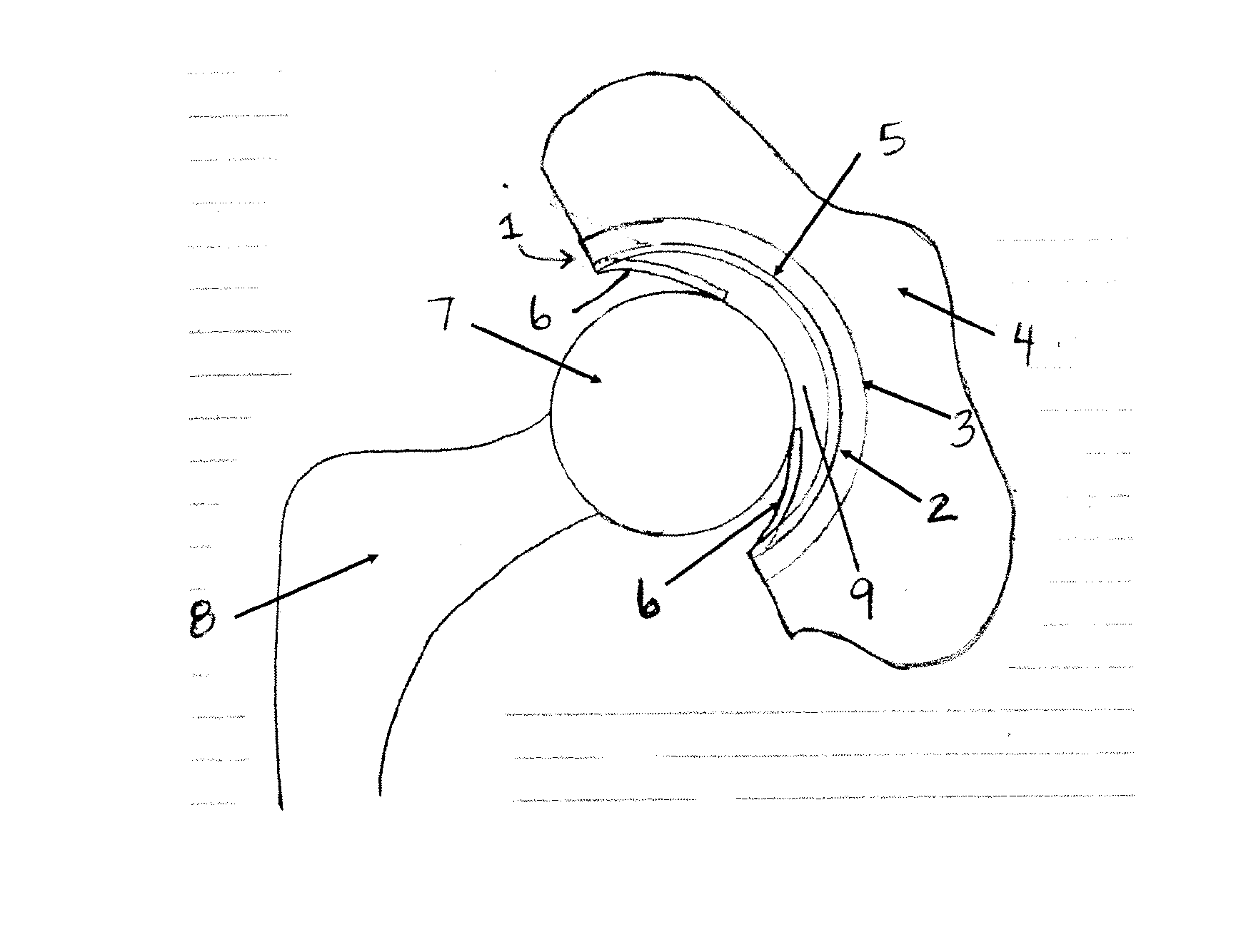
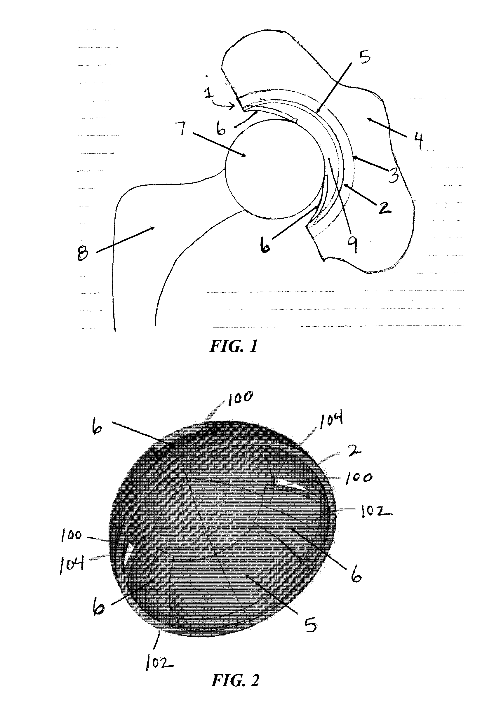
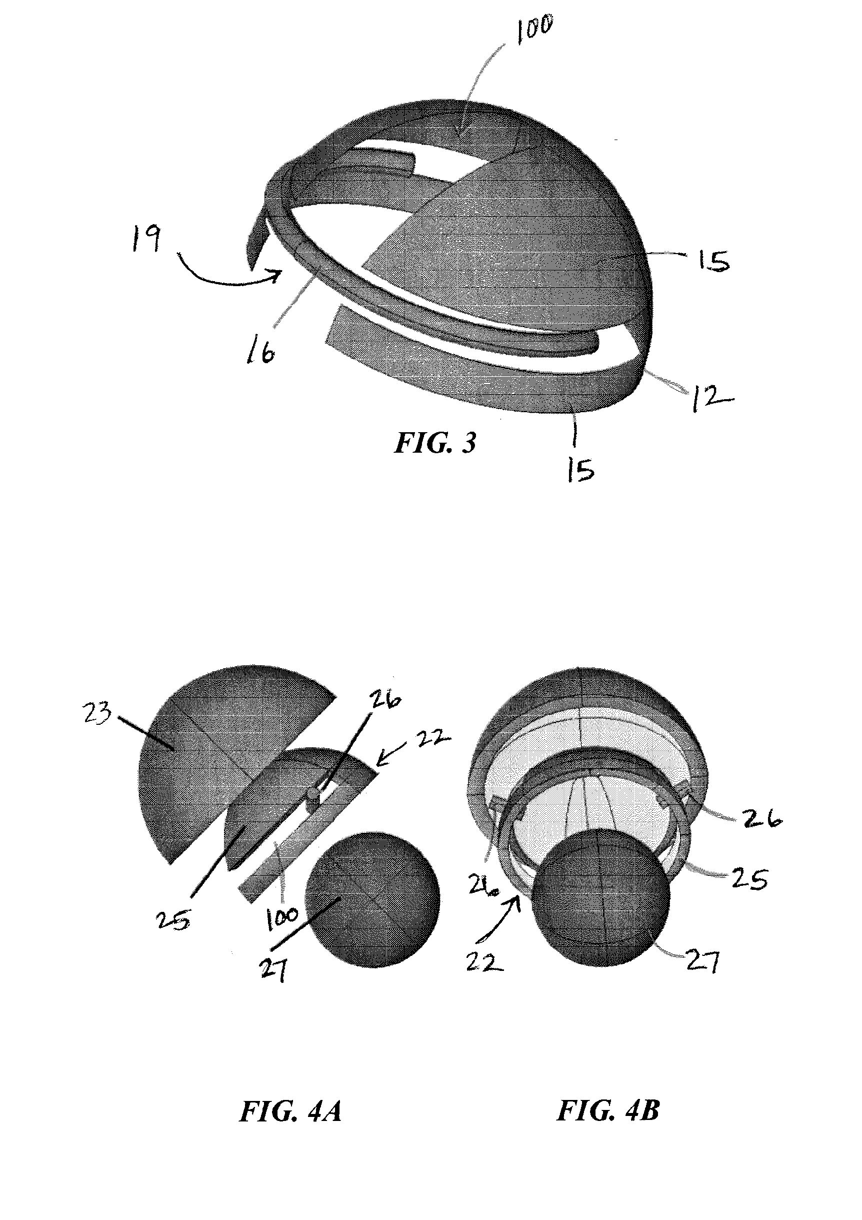
[0091]FIGS. 4A-C show anterior and lateral exploded views of one possible embodiment of the new artificial hip joint as installed in the human body. The acetabular cup is divided into “elastic” and “rigid” elements. Elastic columns in their unstressed state protrude into the ball-cup clearance space and maintain contact with the spherical ball surface over the entire gait cycle. A thin lubricant film is situated between the ball surface and the rigid portion of the cup. (Though the rigid portion of the cup has some inherent compliance, its denotation is meant only to distinguish from the elastic elements which are considerably more compliant.)

[0092]The elastic elements can be fabricated as a continuous piece integrated with the rigid portion of the cup or affixed to the shell backing. The rigid portion of the cup is attached to the shell in the usual manner through connections such as screws, an adhesi...

example 2

Planar Finite Elements

[0123]Formulation

[0124]FIG. 25 shows a planar triangular fluid film element arbitrarily oriented relative to a system X, Y, Z reference frame. The position vector of the element nodes are denoted as Si, i=1, 3, where |Si|=R2=R. Define nodal position vectors relative to the element centroid by

si=Si−(S1+S2+S3) / 3  (A1)

from which a set of orthonormal vectors u, v, n can be formed from

u=s1 / |s1|  (A2)

n=s1×s2 / |s1×s2|  (A3)

v=n×u  (A4)

[0125]Vector n is normal to the element plane. Vectors u and v lie in the element plane and are employed as unit vectors for a ξ, η film reference frame with its origin at the element centroid. Nodal coordinates relative to the film reference frame are thus given by

Piξ=si·u  (A5)

Piη=si·v  (A6)

[0126]Nodal film thickness and its time rate of change are given by

hi=C−e·Si / R  (A7)

dhi / dt=−de / dt·Si / R  (A8)

[0127]For elements which are small compared with the cup radius, n≈Si / R, with the result that nodal ball surface velocity components in the fil...

example 3

Proportional Area Projection

[0137]Consider a differential surface area element (dA)s=R2 sin θdθdφ defined on the hemisphere shown in FIG. A2-A-B with R≡R2. The spherical differential area is mapped onto a plane with projected differential area

(dA)p=rdrdφ  (B1)

[0138]Arbitrarily setting area ratio J≡(dA)p / (dA)s gives

JR2∫0θ sin θdθ=∫0rrdr  (B2)

so that

r / R=(2J)1 / 2(1−cos θ)1 / 2  (B3)

[0139]A point with spatial coordinates X, Y, Z located on a hemispherical surface of radius R will be mapped to coordinates x, y on the plane using the relations

x=r cos φ  (B4)

y=r sin φ  (B5)

where

cos φ=X / (R sin θ)  (B6)

sin φ=Y / (R sin θ)  (B7)

with

cos θ=Z / R  (B8)

sin θ=(1−cos2θ)1 / 2  (B9)

[0140]Simplifying gives

x=X[2J / (1+Z / R)]1 / 2  (B10)

y=Y[2J / (1+Z / R)]1 / 2  (B11)

[0141]Conversely, a point with coordinates x, y on the plane will be mapped to spatial coordinates X, Y, Z on a hemispherical surface of radius R using the relations

X=R sin θ cos φ  (B12)

Y=R sin θ sin φ  (B13)

Z=R cos θ  (B14)

where

cos θ=1−(r / R)2 / (2J)  (B15)

sin ...


PUM


Abstract

The present invention relates to an artificial hip joint replacement system. The system includes an acetabulum portion comprising a cup suitable to be received by a subject's acetabular bone. The cup includes a rigid portion and an elastic portion attached to the rigid portion. Also included in the system is a ball received within the cup and in contact with the elastic portion and a femoral stem attached to the ball. The elastic portion is positioned to cause expansion and contraction of a space between the ball and the rigid portion of the cup so they are further apart from one another during periods of low mechanical loads.

Description

[0001]This application claims the benefit of U.S. Provisional Patent Application Ser. No. 61 / 699,438, filed Sep. 11, 2012, which is hereby incorporated by reference in its entirety.FIELD OF THE INVENTION[0002]The present invention relates to an artificial hip joint replacement system.BACKGROUND OF THE INVENTION[0003]Total hip arthroplasty refers to the replacement of natural hip joint components with artificial ball and socket devices of various complexity and configurations. A generally spherical ball comprised of metallic or ceramic materials is often attached to an artificial femoral stem implanted in the femur, while a generally hemispherical socket is implanted into a surgically modified acetabulum.[0004]Artificial hip joint designs are typically classified according to the paired materials employed in the prosthesis. In “metal-on-metal” designs, both ball and socket are comprised of various metallic alloys (such as stainless steel, CoCr, and CoCrMo), as exemplified in U.S. Pat...

Claims


Application Information

Patent Timeline
Patent Type & Authority Applications(United States)
IPC IPC(8): A61F2/34A61F2/36
CPCA61F2/34A61F2230/0095A61F2230/0093A61F2/36A61F2/32A61F2/3609A61F2002/30253A61F2002/30563A61F2002/30565A61F2002/30571A61F2002/30594A61F2002/30652A61F2002/30673A61F2002/30934A61F2002/30937A61F2002/3225A61F2002/3611A61F2002/3623
Inventor BOEDO, STEPHENBOOKER, JOHN F.
Owner CORNELL UNIVERSITY
Why Eureka
Try Eureka