Tankless water heater

a tankless water heater and tank body technology, applied in the direction of heating types, domestic hot water supply systems, lighting and heating apparatus, etc., to achieve the effect of affecting the service life of the compressor

Inactive Publication Date: 2015-12-03
CHEN JIANLIANG
View PDF11 Cites 5 Cited by
  • Summary
  • Abstract
  • Description
  • Claims
  • Application Information

AI Technical Summary

Benefits of technology

[0024]When water heaters are being used, problems of opening or closing waterway and frequently switching of the water-passing state often exist, in which aspect, different from thermal storage water heater, the tankless water heater has no large-capacity water storage device, thus the heating device usually needs to be opened or closed frequently, while for the air-energy water heater providing heat sources through heat pump circulation, the refrigerant fluid in the heat pump circulation loop after shutdown requires certain time to achieve pressure balance, and if the pressure of the refrigerant fluid in the loop is not balanced, the compressor start-up command will be given, thus causing two consequences: 1) the compressor cannot be opened in time, which may lead the heating capacity of the whole machine to lag behind and disable the water temperature from reaching the preset value; 2) the compressor can be opened, and since high and low pressures of the compressor are not fully balanced, the compressor's service life may be affected. Of the tankless water heater of the present invention, a heating condenser and a pressure relief condenser, on which valves are provided respectively to control the connection state of the two branches, are set in series at the condenser part of the heat pump circulation loop. When the water heater supplies hot water normally, the circuit where the heating condenser lies is opened to make high-temperature high-pressure refrigerant condensed, so as to heat the waterway heating part. When the continuous compressor operation time is insufficient and hot water is not required, close the circuit where the heating condenser lies to stop the heating condenser's heating to the waterway heating part, meanwhile, open the pressure relief condenser to enable the heat pump circulation to continue until the preset working time before closing the compressor, which avoids a compressor emergency shutdown's damage to the equipment.

Problems solved by technology

However, since electric-heated tankless water heaters require high power, in some circuit environments, it does not meet the installation requirements, and for the characteristics of electric heating, the heat conversion efficiency is also unsatisfactory.
Gas-fuelled tankless water heaters are widely used as well, but the fuel gases (natural gas, liquid petroleum gas, or water gas, etc.) used accordingly are non-renewable energies, which cause the waste of valuable natural resources.
Besides, due to insufficient combustion and other causes, this kind of water heater may lead to risks like CO poisoning.
The air-source heat pump heating system applied to the existing air-energy water heater generally consists of three parts, namely the main engine, the water tank, and the heating system; for a household water tank, first, water tanks with a general capacity of 150 to 320 L will occupy a very large part of the building area when being installed, and even if some are mounted outside the wall with supports, due to the weight of the tank itself and the water added in, this installation method is quite dangerous; second, as to the material and technology for the tank liner, no matter whether it is stainless or enamelled, owing to the deficiency of the manufacturing technology, tank leakage cannot be avoided; third, the heat exchanger in the tank is generally made of copper tubing or stainless steel tubing, which in the areas with inferior water quality may be corroded and perforated, leading to refrigerant leakage, which will be fatal for the unit; fourth, since the main engine and the water tank are required to be connected mutually with connecting tubes, it is very difficult to avoid human-made refrigerant leakage in installation; fifth, due to the characteristics of water-storage-type heat pump, it is required to provide a long period to heat the water up to a higher temperature, which cannot satisfy the requirement of instant water supply, besides, in the later period, the water temperature fluctuates significantly, which may affect the comfort of water use; in addition, since the level of condensation temperature determines the energy consumption of the unit, long-term operation under high condensation temperature and pressure of traditional unit with water tank will be a great challenge to the service life of compressor; sixth, if taking storage-type water tank, it is generally required to mix water when using water, which may cause several problems: 1) the hot water in the water tank is of low utilization rate; 2) during heat preservation, the water temperature of the water tank drops inevitably, which may increase energy consumption; 3) when installing water valve at the user's house, it is undoubtedly necessary to mount a water mixing valve, which may increase the material cost; seventh, generally, when the heat for the heating system comes from the water tank, it is required to install a heat exchange coil in the tank to form a closed circuit with floor heating coil or radiator and circulating water pump, which increases the difficulty of tank manufacturing technology and occupies water tank capacity.
Therefore, currently, various water heater solutions in the industry all have their own insurmountable principle defects.

Method used


Image

  • Tankless water heater
  • Tankless water heater
  • Tankless water heater

Examples


Embodiment Construction

[0029]To describe the technical contents, structural features and realization purposes and effects more clearly, the embodiments will be taken to detail the present invention in combination with the drawings.

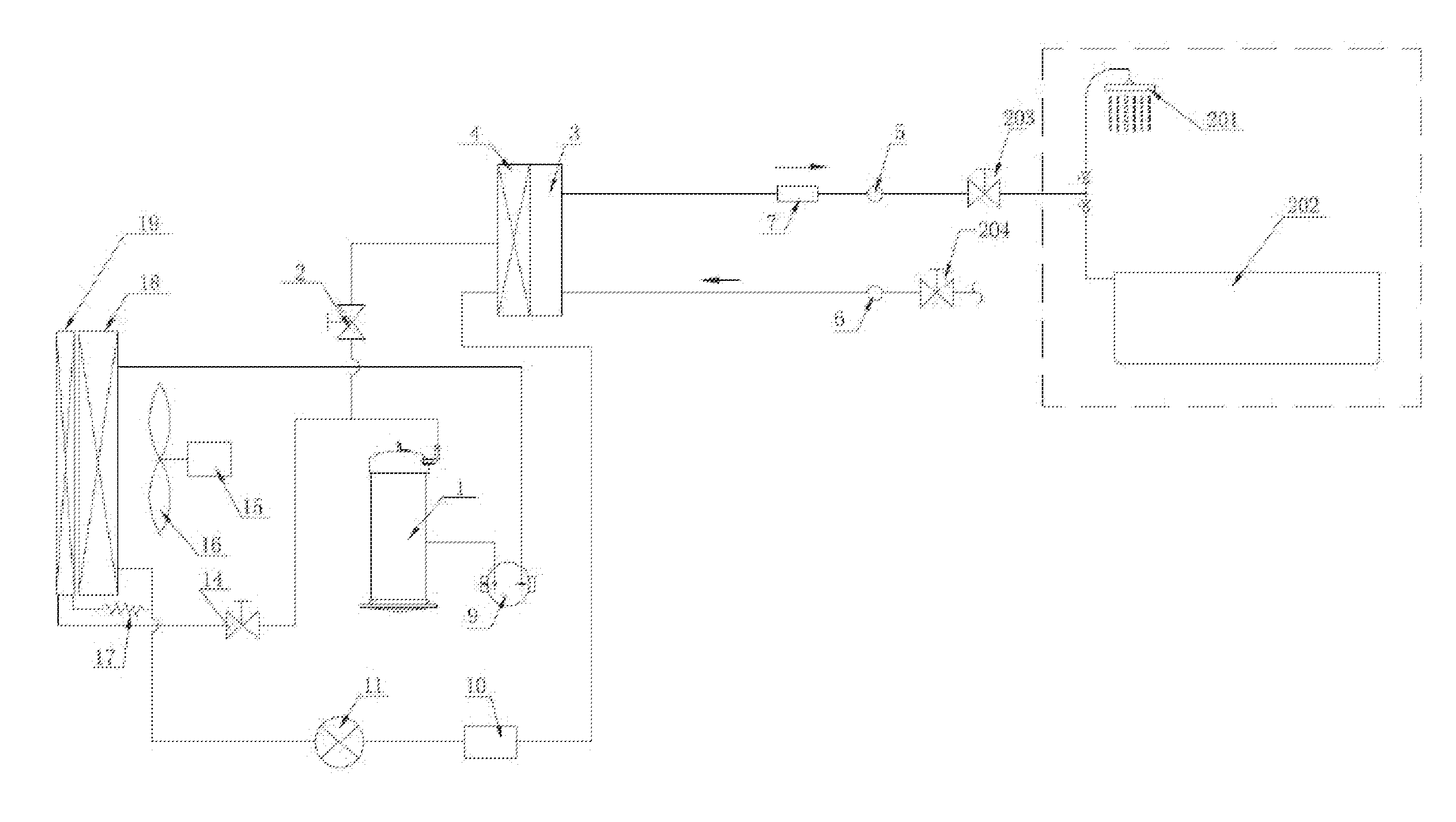
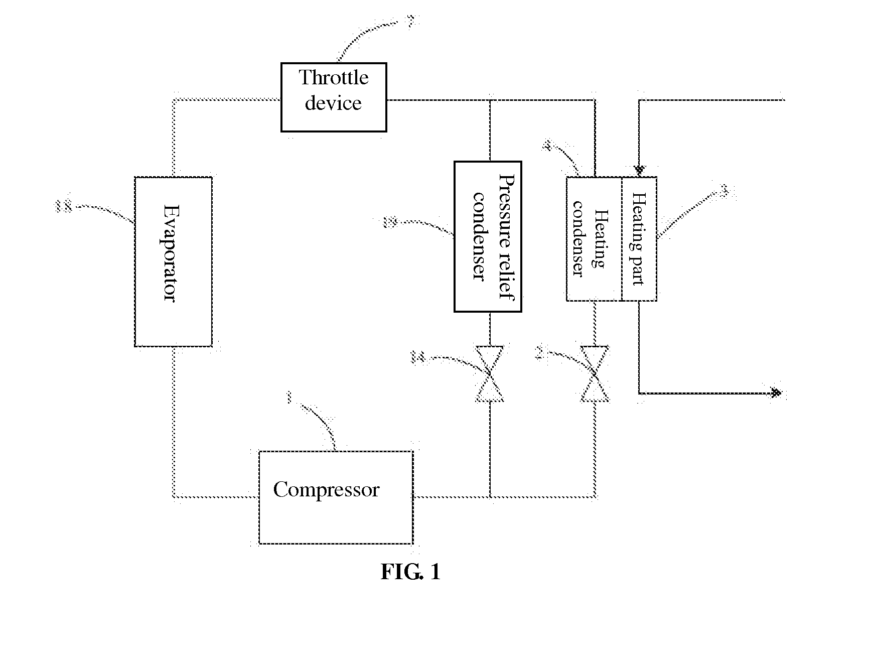
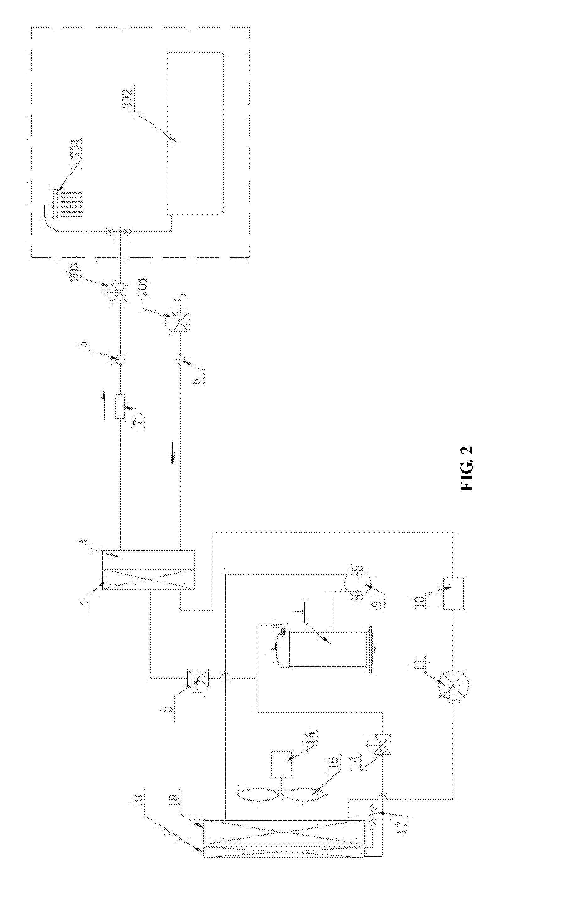
[0030]As shown in FIG. 1 and FIG. 2, the present embodiment provides a tankless water heater, including a controller, a waterway and a heat pump circulation loop;

[0031]In the water-flowing direction, the waterway successively includes: an inlet 6, a heating part 3 and an outlet 5;

[0032]The heat pump circulation loop successively includes: a compressor 1, an evaporator 18, a condenser and a throttle device 7, wherein the compressor is in control connection with the controller, and the condenser includes a heating condenser 4 and a pressure relief condenser 19, wherein the heating condenser 4 is in heat conduction contact with the heating part in the waterway and is set in series with the pressure relief condenser 19 in the heat pump circulation loop, besides, a heating condenser ...


PUM


Abstract

This invention is including a controller, a waterway and a heat pump circulation loop; the waterway, in the water-flowing direction, successively includes: an inlet, a heating part and an outlet; the heat pump circulation loop successively includes: a compressor, an evaporator, a condenser and a throttle device, wherein the compressor is in control connection with the controller, and the condenser includes a heating condenser and a pressure relief condenser, wherein the heating condenser is in heat conduction contact with the heating part in the waterway and is set in series with the pressure relief condenser in the heat pump circulation loop, besides, a heating condenser valve is set in the branch where the heating condenser lies and a pressure relief condenser valve in that where the pressure relief condenser stands, wherein the heating condenser valve and the pressure relief condenser valve are in control connection with the controller.

Description

TECHNICAL FIELD[0001]The present invention relates to a tankless water heater, and more especially, to a heat pump-heated water heater.DESCRIPTION OF THE RELATED ART[0002]Usually, a tankless water heater is also named instantaneous or fast-heating water heater, characterized in that: cold water enters and hot water goes out, for which as along as the outlet valve is opened, hot water can be supplied continuously in a short period, and if not demanding hot water, just close the outlet valve to cut off the waterway and the heating will be suspended within a short time. At present, most tankless water heaters are electric heated and gas fuelled.[0003]The principle of an electric-heated tankless water heater is to use a high-power electric heater to heat the cold water flowing through the heating area up to the predetermined service temperature quickly, so as to achieve the purpose of “cold water in and hot water out”. Since the water storage device on a thermal storage water heater is ...

Claims


Application Information

Patent Timeline
Patent Type & Authority Applications(United States)
IPC IPC(8): F24H9/20F24H4/02
CPCF24H4/02F24H9/2007F24H9/2028F24D17/02F24H15/219F24H15/39F24H15/156F24H15/38
Inventor CHEN, JIANLIANG
Owner CHEN JIANLIANG
Why Eureka
Try Eureka