Optical effect layers showing a viewing angle dependent optical effect; processes and devices for their production; items carrying an optical effect layer; and uses thereof

a technology of optical effect and viewing angle, applied in the field of optical effect layers, can solve the problems of difficult to obtain a highly dynamic, blurred ring edges of “rolling ring” effects, and the problem of increasing the size (diameter), and achieves the effects of easy detection, good sharpness and/or contrast, and easy detection of overt security

Active Publication Date: 2015-12-10
SICPA HLDG SA
View PDF13 Cites 39 Cited by
  • Summary
  • Abstract
  • Description
  • Claims
  • Application Information

AI Technical Summary

Benefits of technology

[0008]Accordingly, it is an object of the present invention to overcome the deficiencies of the prior art as discussed above. This is achieved by the provision of an optical effect layer, e.g. on a document or other item, which exhibits a viewing-angle dependent apparent motion of image features over a

Problems solved by technology

The protection provided by covert security features relies on the concept that such features are difficult to detect, typically requiring specialized equipment and knowledge for detection, whereas “overt” security features rely on the concept of being easily detectable with the unaided human senses, e.g. such features may be visible and/or detectable via the tactile senses while still being difficult to produce and/or to copy.
However, the effectiveness of overt security features depends to a great extent on their easy recognition as a security feature, because most users, and particularly those having no prior knowledge of the security features of a therewith secured document or item, will only then actually perform a security check based on said security feature if they have actual

Method used


Image

  • Optical effect layers showing a viewing angle dependent optical effect; processes and devices for their production; items carrying an optical effect layer; and uses thereof
  • Optical effect layers showing a viewing angle dependent optical effect; processes and devices for their production; items carrying an optical effect layer; and uses thereof
  • Optical effect layers showing a viewing angle dependent optical effect; processes and devices for their production; items carrying an optical effect layer; and uses thereof

Examples


example 1

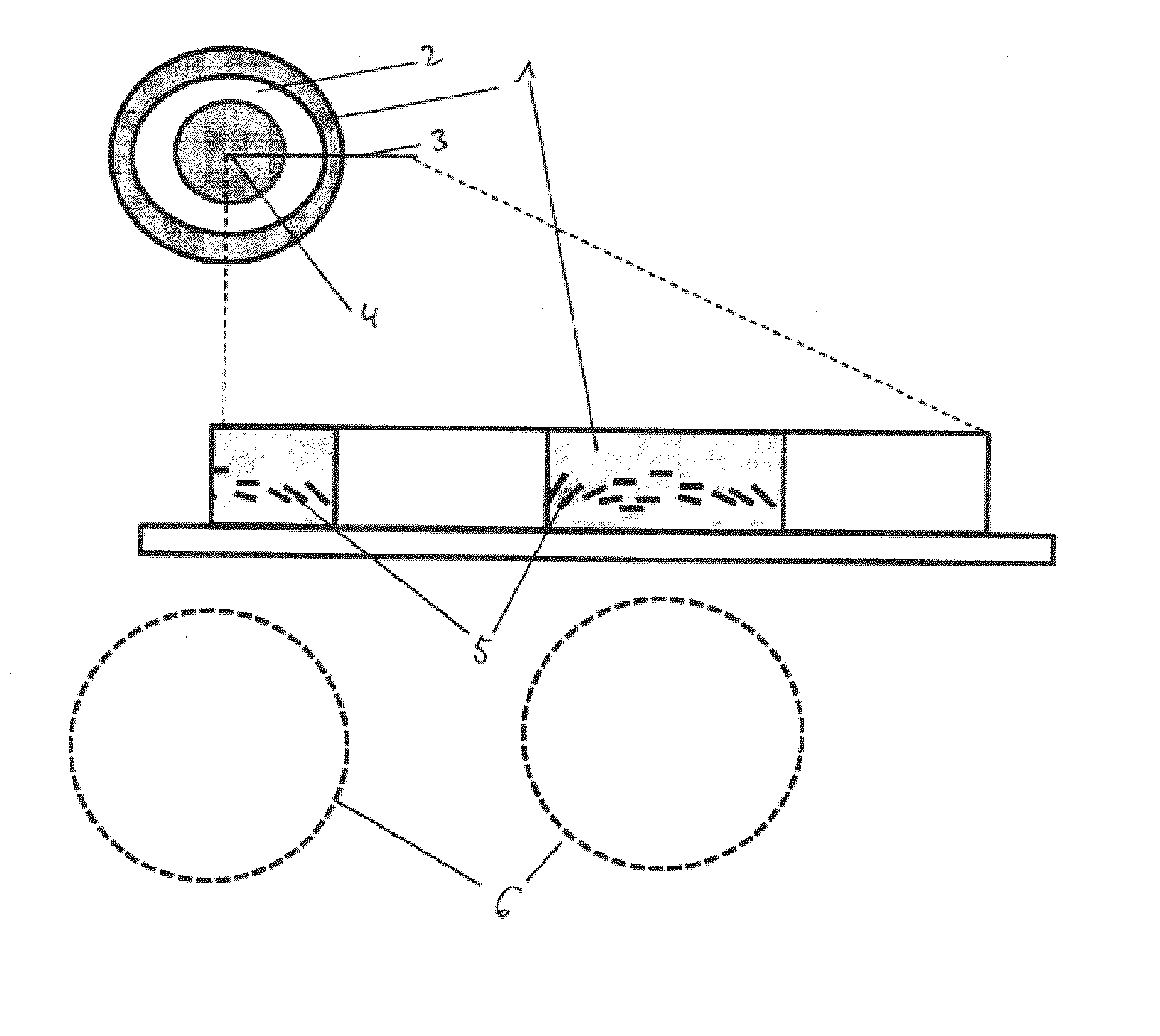
[0204]A magnetic-field-generating device according to FIG. 5 was used to orient non-spherical optically variable magnetic pigments in a printed layer of a UV-curable screen printing ink on a black paper as the substrate.

[0205]The ink had the following formula:

Epoxyacrylate oligomer40%Trimethylolpropane triacrylate monomer10%Tripropyleneglycol diacrylate monomer10%Genorad 16 (Rahn)1%Aerosil 200 (Evonik)1%Irgacure 500 (BASF)6%Genocure EPD (Rahn)2%Non-spherical optically variable magnetic pigments (7 layers) (*)20%Dowanol PMA10%(*) green-to-blue optically variable magnetic pigment flakes of diameter d50 about 15 μm and thickness about 1 μm, obtained from JDS-Uniphase, Santa Rosa, CA.

[0206]The magnetic-field-generating device comprised a ground plate of soft-magnetic iron, on which an axially magnetized NdFeB permanent magnetic cylinder of 5 mm diameter and 8 mm thickness was disposed, with the magnetic South Pole on the soft-magnetic ground plate. A rotationally symmetric, U-shaped sof...

example 2

[0209]A magnetic-field-generating device according to FIG. 9 was used to orient optically variable magnetic pigments in a printed layer of a UV-curable screen printing ink according to the formula of Example 1 on a black paper as the substrate.

[0210]The magnetic-field-generating device comprised two NdFeB magnets of 10 mm large, 10 mm width, and 10 mm height, spaced 15 mm from each other, having their magnetization directions along the width of 10 mm. The magnets were radially aligned about the rotation axis so that their magnetization directions were collinear. The magnets were mounted on a plate rotating at the speed of 300 rpm (rotations per minute). The paper substrate carrying the printed layer of a UV-curable screen printing ink was disposed at a distance of 0.5 mm from the surface of magnets. The so obtained magnetic orientation pattern of the optically variable pigment particles was, subsequently to the applications step, fixed by UV-curing the printed layer comprising the p...


PUM


Abstract

The invention relates to the field of the protection of security documents such as for example banknotes and identity documents against counterfeit and illegal reproduction. In particular, the invention relates to optical effect layers (OEL) showing a viewing-angle dependent optical effect, devices and processes for producing said OEL and items carrying said OEL, as well as uses of said optical effect layers as an anti-counterfeit means on documents. The OEL comprises a plurality of non-spherical magnetic or magnetizable particles, which are dispersed in a coating composition comprising a binder material, wherein in at least a loop-shaped area of the OEL at least a part of the plurality of non-spherical magnetic or magnetizable particles are oriented such that their longest axis is substantially parallel to the plane of the OEL, and wherein, in a cross-section perpendicular to the OEL and extending from the centre of the central area, the longest axis of the oriented particles present in the loop-shaped area forming the impression of the loop-shaped body follow a tangent of either a negatively curved or a positively curved part of a hypothetical ellipse or circle.

Description

FIELD OF THE INVENTION[0001]The present invention relates to the field of the protection of value documents and value commercial goods against counterfeit and illegal reproduction. In particular, the present invention relates to optical effect layers (OEL) showing a viewing-angle dependent optical effect, devices and processes for producing said OEL and items carrying said OEL, as well as uses of said optical effect layers as an anti-counterfeit means on documents.BACKGROUND OF THE INVENTION[0002]It is known in the art to use inks, compositions or layers containing oriented magnetic or magnetizable particles or pigments, particularly also magnetic optically variable pigments, for the production of security elements, e.g. in the field of security documents. Coatings or layers comprising oriented magnetic or magnetizable particles are disclosed for example in U.S. Pat. No. 2,570,856; U.S. Pat. No. 3,676,273; U.S. Pat. No. 3,791,864; U.S. Pat. No. 5,630,877 and U.S. Pat. No. 5,364,689....

Claims


Application Information

Patent Timeline
IPC IPC(8): B42D25/369B44F1/10H01F41/16G07D7/00H01F7/02
CPCB42D25/369G07D7/0006B42D2033/16H01F41/16B44F1/10H01F7/0273B42D2033/20B42D2035/20B05D3/20B05D3/207B41M3/148B42D25/29G07D7/003B05D3/00
Inventor SCHMID, MATHIEULOGINOV, EVGENYDESPLAND, CLAUDE ALAINDEGOTT, PIERRE
Owner SICPA HLDG SA
Why Eureka
Try Eureka