
Subsurface multiple antenna radiation technology (SMART)

a multi-antenna radiation and subsurface technology, applied in the direction of survey, insulation, borehole/well accessories, etc., can solve the problems of many remedial technologies ineffective or ineffective, difficult to remove many pollutants or toxic materials, and difficult to escape gas through the pore spaces, etc., to enhance oil and gas recovery, enhance fluid permeability, and expand the porosity and permeability of formation

Inactive Publication Date: 2015-12-10
TURBOSHALE INC
View PDF6 Cites 7 Cited by
  • Summary
  • Abstract
  • Description
  • Claims
  • Application Information

AI Technical Summary

Benefits of technology

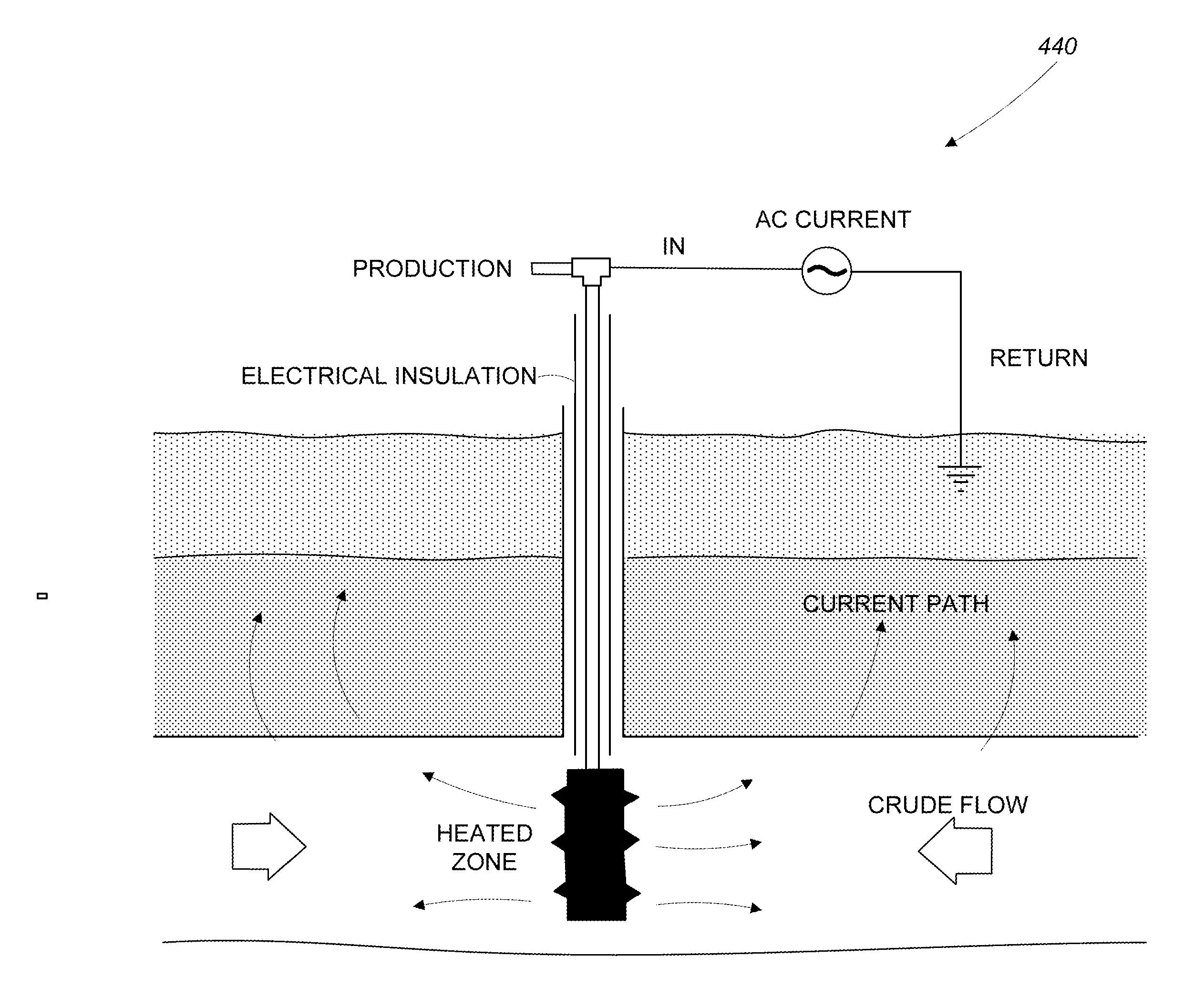
The patent text describes a system that uses high power radiofrequency to change the properties of material during thermal treatment. This can include altering the chemical bonds and structure of materials to make them more energy efficient for gas recovery. The system can also improve heavy oil recovery by reducing its viscosity and enhancing its mobility. The text also mentions the use of the RAGD method, which replaces steam with radioenergy to improve oil drainage in heavy oil environments. The patent describes the use of a SMART antenna to provide the radiofrequency heating. The SMART antenna can also employ transversely polarized radiators to produce a field in which the electric field vector lies in planes normal to the axis of the radiofrequency antenna.

Problems solved by technology

However, the gas has difficulty escaping through the pore spaces because they are too small, poorly connected, or non-existent to provide gas recovery pathways
Removal of many pollutants or toxic material is especially difficult when the contaminants enter bedrock fractures.
For example, The heterogeneous distribution of residual 1,1,1-trichloroethane (TCA) dense nonaqueous phase liquid (DNAPL) within discrete, poorly connected bedrock fractures renders many remedial technologies inefficient or ineffective because the DNAPL cannot be physically removed or reached to treat in situ.
Thermal resistivity heating and thermal conduction heating can treat a targeted volume of bedrock, overcoming the physical constraints of the bedrock fracture network, but can be prohibitively expensive to implement due to energy requirements for heating the rock mass.

Method used


Image

  • Subsurface multiple antenna radiation technology (SMART)
  • Subsurface multiple antenna radiation technology (SMART)
  • Subsurface multiple antenna radiation technology (SMART)

Examples


Embodiment Construction

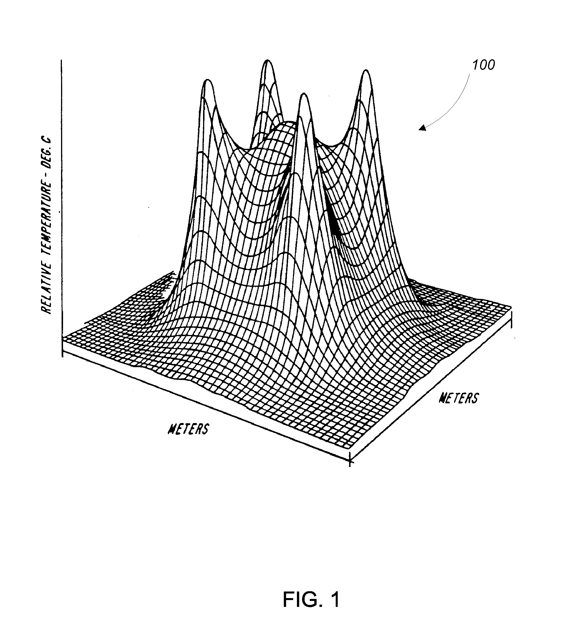
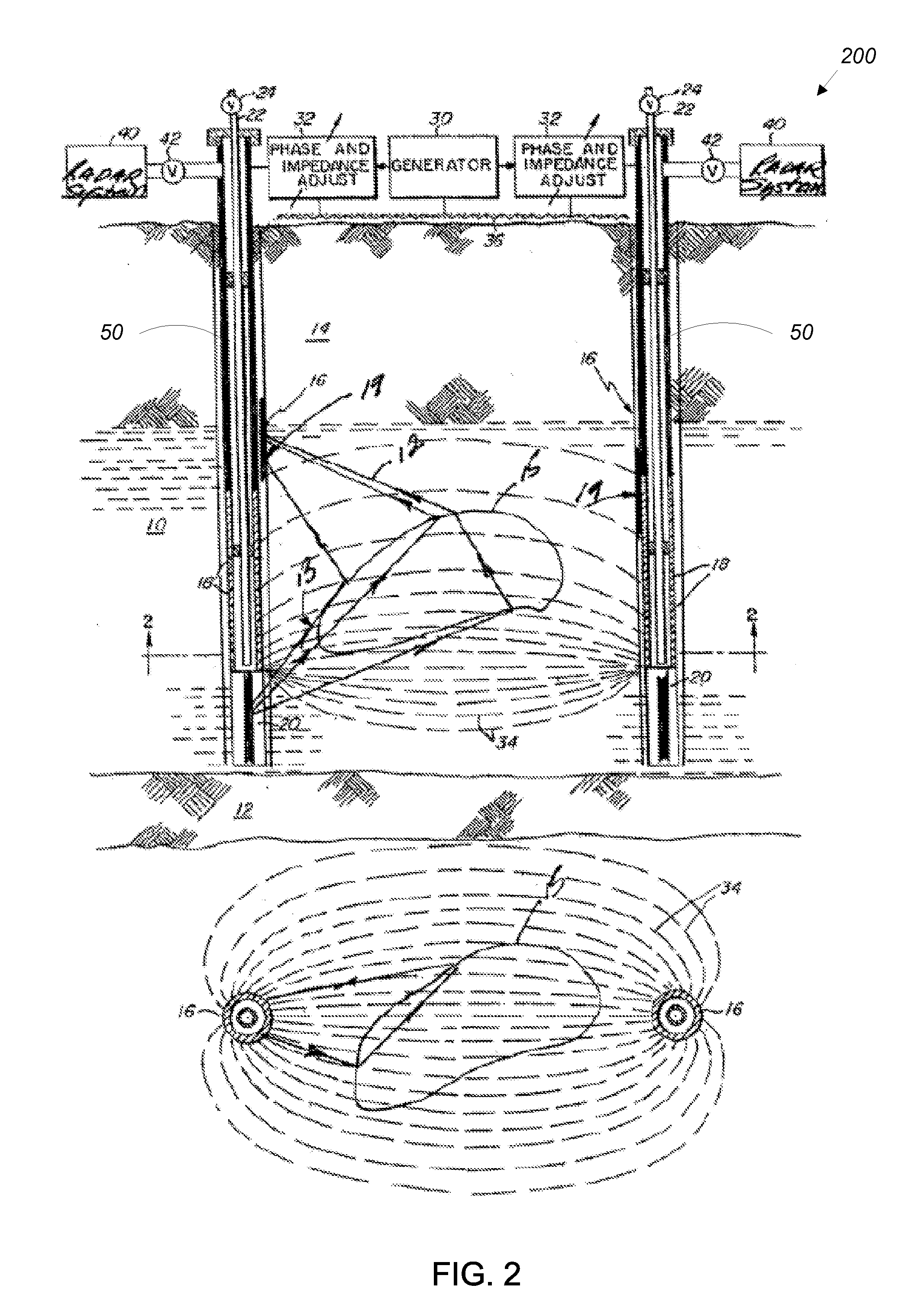
[0050]Aspects described herein relate to systems for sub-surface, the systems including high power radiofrequency heating antennas collocated with radar antennas. In general, the collocated antennas are inserted into boreholes which may be of the vertical or horizontal type as indicated in U.S. Pat. No. 7,891,421 by Kasevich. The collocated antennas may be positioned at various depths down to several thousand feet and at frequencies of operation that may range from hundreds of kilohertz 50 MHz. Power levels for the system may vary from 5 kilowatts to 1 megawatt for CW and if pulse power is used, the duty cycle may range from 0.0001 to 0.1 as an example. Referring to FIG. 1, one possible heating pattern 100 for a four heating antenna system in which the antenna boreholes with collocated radar are spaced ½ wavelength apart on square is illustrated. Such a pattern of heat is described in U.S. Pat. No. 5,199,488 by Kasevich. At one MHz in an oil shale material, the square is 50 meters b...


PUM


Abstract

An in-situ radar guidance system with a collocated high power electromagnetic heating system or SMART System (Subsurface Multiple Antenna Radiation Technology) creates chemical, physical, and electrical changes as needed to certain organic or inorganic materials for energy efficient recovery of liquids, gases, and solids.

Description

CROSS REFERENCE TO RELATED APPLICATIONS[0001]This application claims priority to U.S. Provisional Application No. 62 / 009,482, filed on Jun. 9, 2014 and U.S. Provisional Application No. 62 / 017,408, filed on Jun. 26, 2014, the contents of which are hereby incorporated by reference in their entirety.BACKGROUND[0002]A combination of measurement and control techniques is being increasingly used in the oil industry to capture fluid dynamics in the far-field (several meters) of well bores as it has the potential to significantly improve oil and gas production. This is due to the recent development of oil well technology which allows zonal production control and monitoring in real time through respectively, inflow control valves and down hole sensors. Inflow control valves are capable of imposing a pressure profile along the well that can influence the flow behavior. The advantage of this type of proactive control is that potential problems such as the approach of unwanted fluids or migrati...

Claims


Application Information

Patent Timeline
IPC IPC(8): E21B43/24E21B47/09
CPCE21B47/09E21B43/24
Inventor KASEVICH, RAYMONDRONG, JEB
Owner TURBOSHALE INC
Learn More