
Flywheel energy storage oil pumping machine

Inactive Publication Date: 2015-12-17
QIU YONGAN
View PDF4 Cites 0 Cited by
  • Summary
  • Abstract
  • Description
  • Claims
  • Application Information

AI Technical Summary

Benefits of technology

The present invention provides a flywheel energy storage oil pumping machine with simple structure, small size, lower energy consumption, high efficiency, low failure rate, and no pollution to the power grid. The machine uses a rotary spindle and an energy adjustment flywheel to store and release energy during the pumping process. The energy feedback device controls the speed of the sucker rod during the down stroke to make the down stroke stable and decrease impact. The oil pumping machine does not require a balance system or other essential components of existing oil pumping machines, which simplifies its structure and increases its reliability. The energy feedback device transfers the energy generated during the lowering of the sucker rod to the energy adjustment flywheel and converts it into accelerated rotation to achieve energy storage. The oil pumping machine has a high efficiency, low installed capacity of the electric motor, no pollution to the power grid, low failure rate, and high reliability.

Problems solved by technology

There are many transfer links, resulting in high energy consumption and serious waste.
During the operating of such oil pumping machines, the work done by the oil pumping machines is not uniform due to their structural features.
Therefore, the installed capacity of the electric motor is large, generally multiple times larger than actually required average power, and even above 7 times. Meanwhile, due to the starting characteristics of the electric motor, there is a large impact to the power grid, thereby causing serious pollution to the power grid.

Method used


Image

  • Flywheel energy storage oil pumping machine
  • Flywheel energy storage oil pumping machine
  • Flywheel energy storage oil pumping machine

Examples


embodiment 1

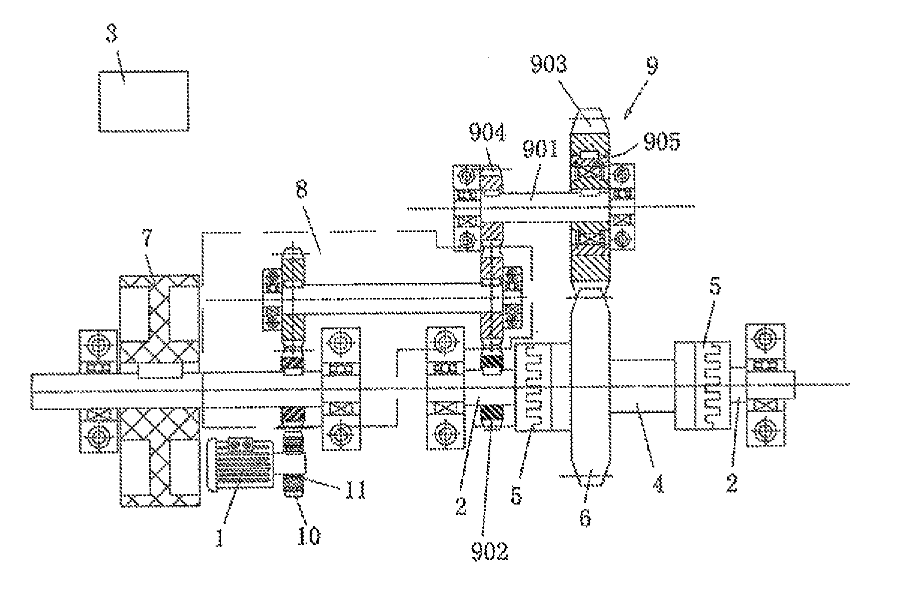
[0037]Referring to FIG. 1, a flywheel energy storage oil pumping machine comprises an electric motor 1 and a control device 3, and further comprises a rotary spindle 2, a lifting roller 4, a roller drive wheel 6, an energy adjustment flywheel 7, a transmission 8, and an energy feedback device 9. The control device 3 comprises a PLC (Programmable Logic Controller), a position switch, a connection cable, etc., and is used for controlling the action of the whole oil pumping machine. The electric motor 1 may be a general electric motor or a variable-frequency electric motor. The rotary spindle 2 is an integral spindle. Of course, the rotary spindle 2 may be one formed by integrating a plurality of split spindles via couplers or by welding or other manners.

[0038]The electric motor 1 drives the rotary spindle 2 to rotate. The lifting roller 4 is connected to a sucker rod (not shown) via a soft connector. The sucker rod is driven to rise by the forward rotation of the lifting roller 4, whi...

embodiment 2

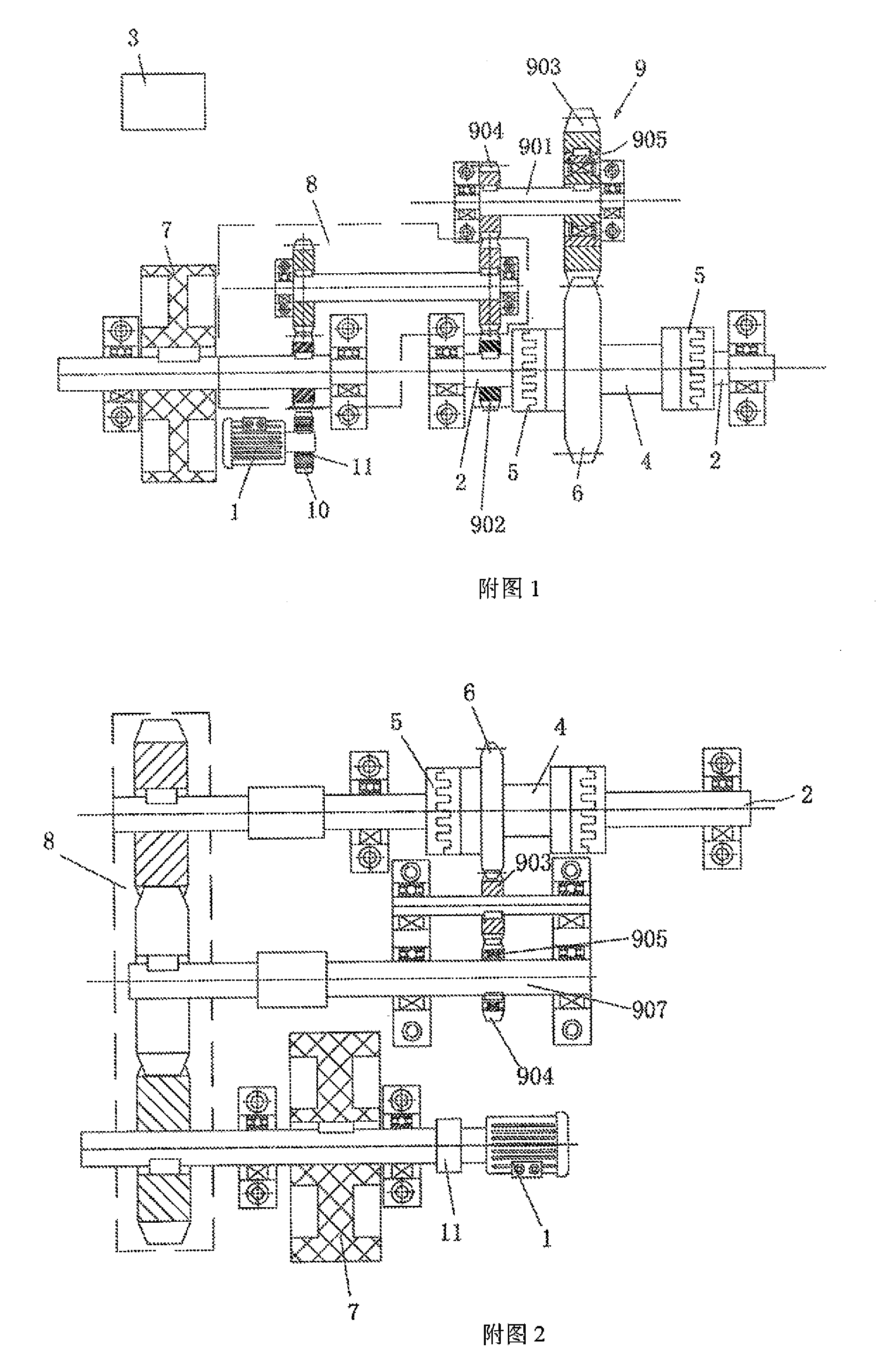
[0042]Referring to FIG. 2, in this embodiment, the energy feedback device 9 is of another structure, and the transmission 8 will be changed in structure with the structure change of the energy feedback device 9. The energy feedback device 9 comprises a rotating shaft 907, a first drive wheel 903 and a second drive wheel 904. The transmission 8 is a multi-stage transmission, and further has a plurality of connecting ends other than the high-speed end and the low-speed end. The connecting shaft of one of the connecting ends is fixedly connected to the rotating shaft 907. Of course, the rotating shaft 907 may be a part extending from the connecting end. The rotating shaft 907 is connected to the second drive wheel 904 via an energy feedback clutch 905, wherein, the energy feedback clutch 905 is a sprag overrun clutch. The first drive wheel 903, the second drive wheel 904 and the roller drive wheel 6 are gears. The first drive wheel 903 is positioned between the roller drive wheel 6 and...

embodiment 3

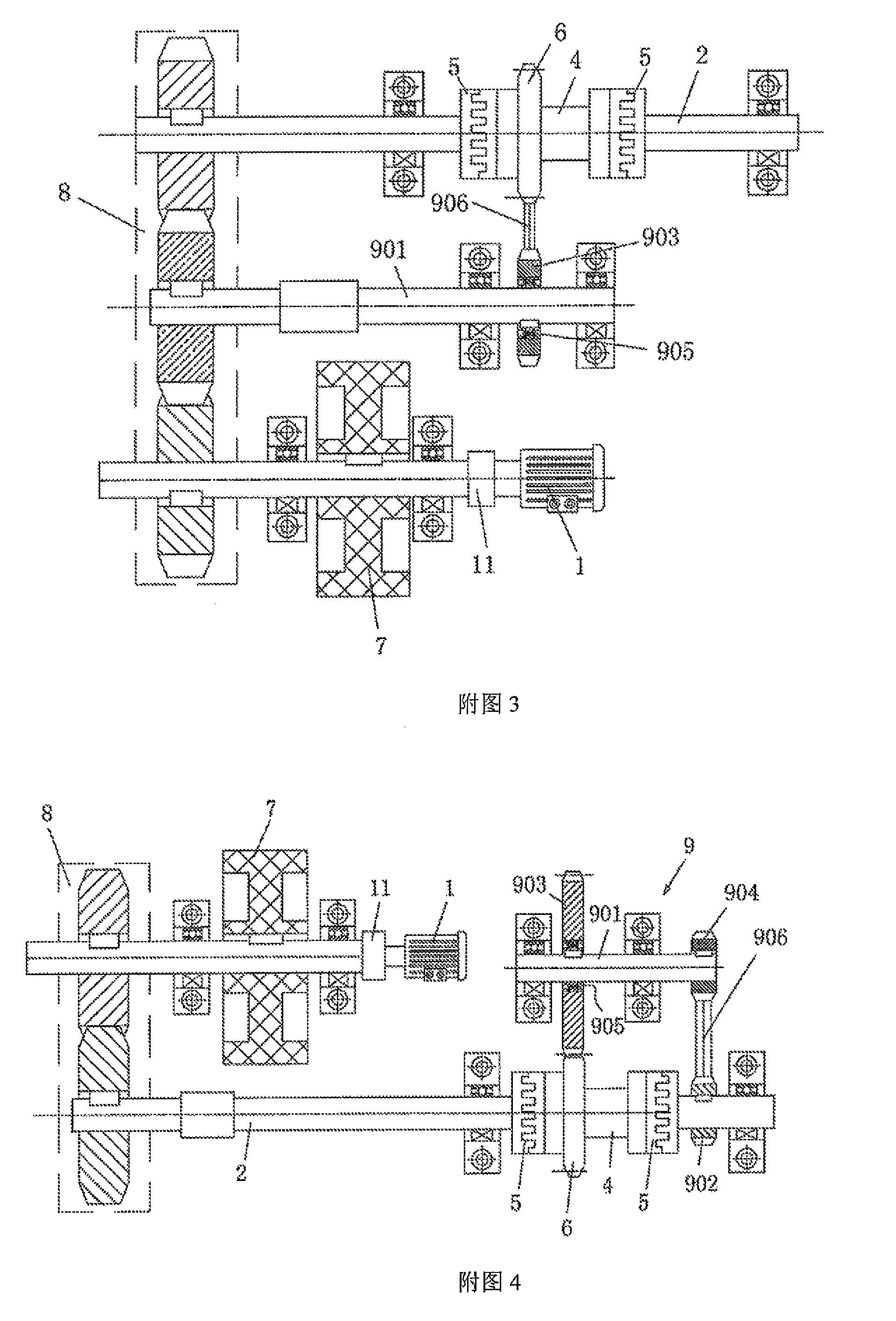
[0043]Referring to FIG. 3, the energy feedback device 9 comprises a drive shaft 901. The drive shaft 901 is connected to a first drive wheel 903 via an energy feedback clutch 905. The transmission 8 further has a plurality of connecting ends other than the high-speed end and the low-speed end. The connecting shaft of one of the connecting ends is fixedly connected to the drive shaft 901. Of course, the drive shaft 901 may be a part extending from the connecting end. The energy feedback clutch 905 is an overrun clutch. The first drive wheel 903 is connected to the roller drive wheel 6 via a driving belt 906. The remaining is the same as Embodiment 2.


PUM


Abstract

Disclosed is a flywheel energy storage oil pumping machine, comprising an electric motor (1) and a control device (3), and also comprising a rotary spindle (2), a lifting roller (4) for lifting an oil sucker rod, a roller drive wheel (6), an energy adjustment flywheel (7), a transmission (8) and an energy feedback device (9), wherein the lifting roller (4)is sheathed on the rotary spindle (2), and the separation and reunion between the rotary spindle (2) and the lifting roller (4) are achieved via a clutch (5); the roller drive wheel (6) is fixedly connected to the lifting roller (4); and a low-speed end of the transmission (8) is connected to the rotary spindle (2), and a high-speed end is connected to the energy adjustment flywheel (7). The flywheel energy storage oil pumping machine is simple in structure, low in cost, small in size, light in weight, small installation capacity of an electric motor, low in energy consumption, high in efficiency and low in failure rate, and has nearly no pollution in a power grid.

Description

TECHNICAL FIELD[0001]The present invention relates to the technical field of oil production equipment for an oil field, more particularly to a flywheel energy storage oil pumping machine.BACKGROUND[0002]The working principle of an oil pumping machine with a sucker rod is pumping petroleum out from an oil well through the vertical up-and-down movement of the sucker rod. An oil pumping machine with a sucker rod in the prior art generally comprises a speed reducer, a balance system, a reversing device and various mechanical driving devices. The energy transfer way of such an oil pumping machine with a sucker rod is: electric motor-belt wheel-speed reducer-balance system-reversing device-various mechanical driving devices. There are many transfer links, resulting in high energy consumption and serious waste. During the operating of such oil pumping machines, the work done by the oil pumping machines is not uniform due to their structural features. In the up-and-down stroke of such an oi...

Claims


Application Information

Patent Timeline
IPC IPC(8): E21B43/12
CPCE21B43/126F16H33/02
Inventor QIU, YONGAN
Owner QIU YONGAN
Learn More