

Switching element driving circuit
a driving circuit and switching element technology, applied in the direction of pulse generator, emergency protective arrangement for limiting excess voltage/current, pulse technique, etc., can solve the problems of long delay time, easy influence of high-speed response time, and difficult control response time via differential amplifier amp, so as to improve control responsiveness, improve control responsiveness, and improve the effect of gate voltag
- Summary
- Abstract
- Description
- Claims
- Application Information
AI Technical Summary
Benefits of technology
Problems solved by technology
Method used
Image

Examples
Embodiment Construction
[0026]A switching element driving circuit according to an embodiment of the present invention will now be described with reference to the drawings.
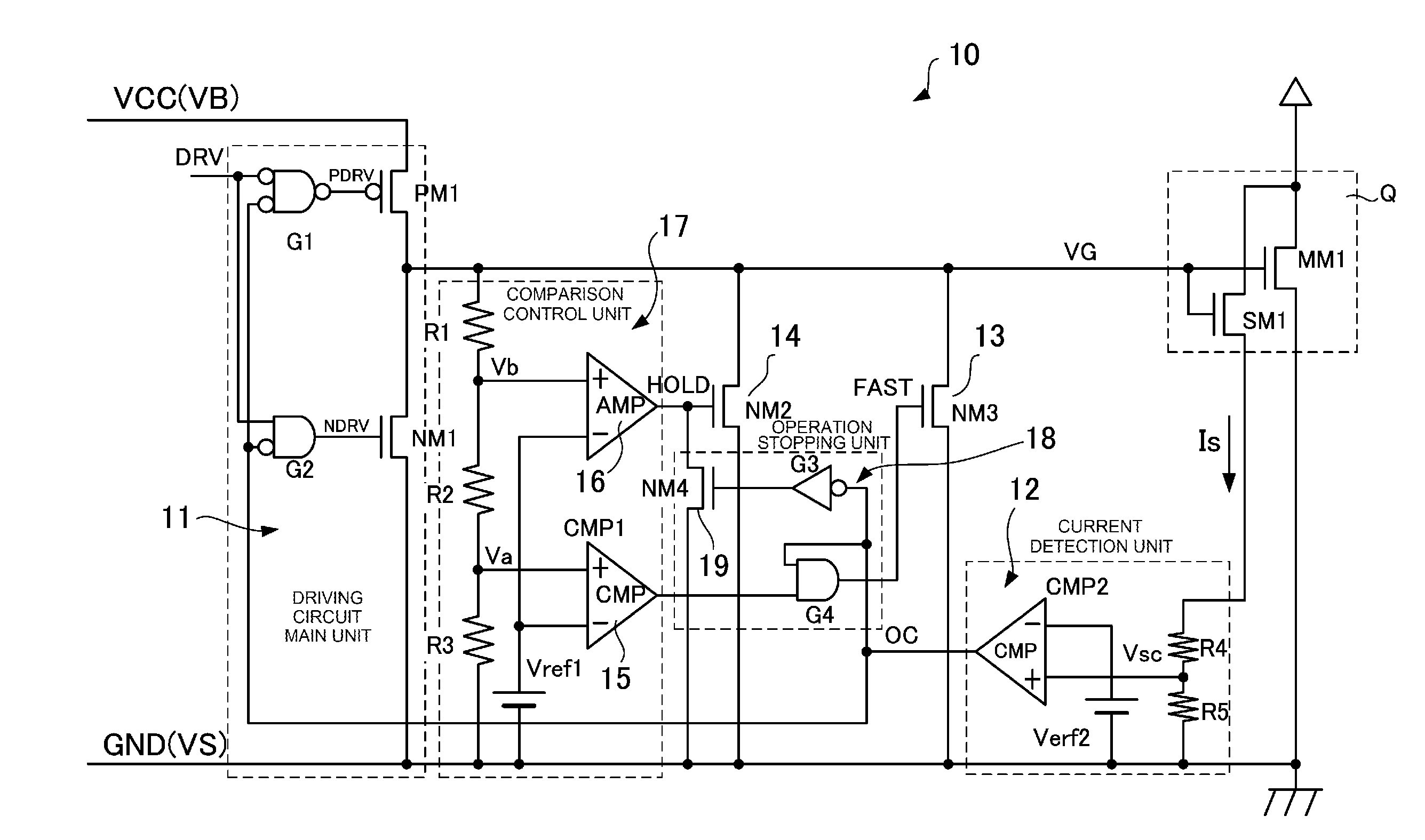
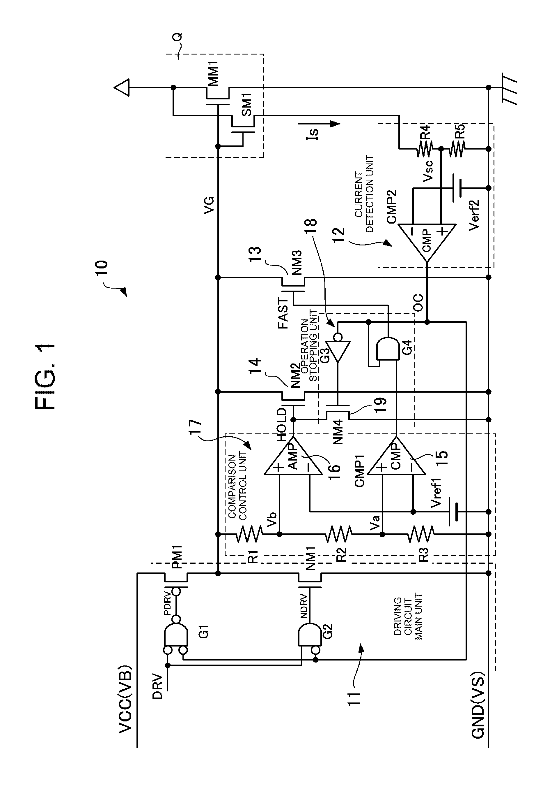
[0027]FIG. 1 is a schematic block diagram depicting a key section of the switching element driving circuit 10 according to the embodiment, where Q is a switching element driven by the switching element driving circuit 10. This switching element Q is constituted by an n-channel high voltage MOS-FET (MM1), for example, and includes a MOS-FET (SM1) for current detection which is connected in parallel. The MOS-FET for current correction (SM1) includes a channel region that is [1 / n] of the high voltage MOS-FET (MM1), and outputs [1 / 100] current Is, for example, that is in proportion to the current flowing through the high voltage MOS-FET (MM1).
[0028]The switching element driving circuit 10 is configured so as to operate by receiving power supply voltage VCC, of which reference potential is the ground potential (GND), for example. To drive the ...
PUM
 Abstract
Description
Claims
Application Information