Hermetically sealed implant sensors with vertical stacking architecture

a technology of implant sensors and stacking structures, which is applied in the field of hermetically sealed implant sensors with vertical stacking architecture, can solve the problems of affecting the vision of the affected eye, irreversible blindness if left untreated, and approximately 10 million physician visits each year, so as to reduce patient complications, quick and easy implantation procedures, and reduce health care costs. the effect of 1.5 billion dollars annually

Active Publication Date: 2016-01-07
INJECTSENSE INC
View PDF9 Cites 18 Cited by
  • Summary
  • Abstract
  • Description
  • Claims
  • Application Information

AI Technical Summary

Benefits of technology

[0009]Embodiments of the present invention provide improved micro-electrical mechanical system (MEMS) based pressure sensor implants for the accurate measurement of physiological signals, such as IOP, on a continuous or frequent basis for appropriate treatment of glaucoma. A particular advantage of the present invention is the implant architecture design and construction which allows the implant form factor (e.g., dimension, size, shape, volume, etc.) to be significantly reduced. This ultra-miniature form factor is important for several reasons.
[0010]For example, the ultra-miniature form factor allows for implantation of the MEMS implant through an injector, syringe, or like delivery systems having a gauge of 19 (e.g., inner diameter of approximately 690 microns) or higher (e.g., up to 28 or 29 gauge). This in turn enables a relatively quick, easy, and safe implantation procedure in an outpatient environment (e.g., 5-10 minutes of surgical time), such as the physician's office, without major invasive surgery which likely results in significant savings to the health system and reduced patient complications. Further, the reduced invasiveness of an injectable pressure sensor implant allows for diagnosis of not only glaucoma patients, but also pre-glaucoma patients. Early diagnosis and follow-up medical therapy could prevent complicated glaucoma surgery (e.g., laser surgery, trabeculectomy, valve implants), vision impairments, and / or blindness in the later years. As most ophthalmologist are well trained in injectables for drug therapies, such as injection of anti-VEGF drugs associated with treatment of age related macular degeneration, adoption of injectable pressure sensor implants should also be relatively well accepted.
[0011]Another benefit of the ultra-miniature form factor is that it allows the MEMS implant to be safely and effectively implanted entirely within a desired location within the eye so as to directly measure IOP levels. Accurate IOP profiles are beneficial for guiding appropriate, safe, and effective therapies for glaucoma control and management, which may include therapeutic pharmaceuticals, implantable shunt or drainage devices, glaucoma surgery, and / or the like. Such implantable IOP pressure sensors further monitor patients for continued compliance with the prescribed treatments, which can be particularly of benefit in medically controlled IOP patients.
[0012]It will be appreciated, however, that the implant devices of the present invention are not limited to solely the ophthalmology space and the diagnosis and treatment of glaucoma, but may find beneficial application in several other medical fields where it is desirable to have an ultra-miniature, injectable implant that provides diagnostic transducer measurements accurately, adjustably, and continuously. For example, such other physiological applications include but are not limited to sensing of an intracranial pressure, a cardiovascular pressure at a location such as the pulmonary artery, and monitoring of glucose, urology parameters such as abdominal compartment syndrome diagnosed with bladder pressure, eye motion controlled or uncontrolled with conditions like horizontal, vertical or torsional nystagmus, or acute compartment syndrome when a patient is under severe trauma condition such broken leg which is causing excessive pressure builds up inside an enclosed space (measured in terms of strain) within the muscle tissue such as arms, legs. At least some of these physiological sensors may utilize one or more additional sensors on the implantable sensor device.
[0013]In many embodiments of the present invention, vertically stacked and hermetically sealed implantable pressure sensor devices for measuring a physiological signal of a patient or animal are described. The implantable device comprises a first wafer and a second wafer. The first wafer comprises at least a pressure sensor configured to measure the physiological signal. The second wafer comprises at least a digitizing integrated circuit. The first wafer is vertically stacked or disposed over the second wafer so as to form a hermetic seal. In particular, the vertical stacking of the wafers is configured to create a hermetically sealed cavity between the first and second wafers.
[0014]This vertical stacking architecture design and construction, which is described in greater detail below, allows for the implant to define its own hermetic package and significantly reduce its form factor so as to be easily implanted as an injectable and within a desired location within the eye. In particular, the implantable device may comprise a size or shape capable of implantation through an injector or syringe having a gauge of 19 or higher. The implantable device may also be sized or shaped to be positionable within a vitreous body of an eye so as to measure an IOP of a vitreous humour which provides a safe region within the physiology of the eye. Other locations such as the anterior chamber where the aqueous humour accumulated can be also directly monitored but at a greater risk to impair the vision of the patient. Monitoring the anterior chambers directly is not worth the risk of affecting vision significantly or the associated liability. Even if there were a slight degradation or attenuation in IOP when measuring within the vitreous humour, the increased pressure may be detected with a continuous pressure profile that will satisfactorily quantify the increase in pressure. The proposed measurement locations can be readily validated across a range of animal models, which may also be used to adjust the sensor sensitivity if necessary.

Problems solved by technology

Glaucoma is associated with elevated levels of intraocular pressure (IOP) and can permanently damage vision in the affected eye(s) and lead to irreversible blindness if left untreated.
In the United States alone, there are about 2.2 million patients with glaucoma resulting in approximately 10 million physician visits each year and health care costs of about 1.5 billion dollars annually.
While tonometry techniques are generally low cost, easy, and non-invasive, a number of different types of errors can significantly reduce the accuracy of this diagnostic tool and as such potentially result in inappropriate diagnosis and / or ineffective follow-up medical treatment.
For example, at least some of these non-invasive clinical techniques may not detect elevated IOP levels (e.g., pressure spikes) as only a single point measurement is taken during an eye exam.
Failure to continuously and / or frequently monitor IOP levels outside the eye clinic (e.g., more than four to six measurements per year) may lead to inaccurate detection of the patient's real IOP profile (e.g., real IOP may be higher or lower than measured IOP).
Non-invasive measurements in some instances also lack accuracy as these devices measure pressure of the eye with an external sensor that provides an indirect measurement of the actual pressure inside the eye.
Hence, the indirect IOP measurements from such non-invasive devices may differ from the actual IOP inside the eye (e.g., overestimated or underestimated) which may lead to inappropriate diagnosis and / or follow-up treatment.
Further, it often inconvenient and unpractical for patients to visit the eye clinic on a strict regular schedule for IOP measurement.
Although implantable IOP devices have been proposed for direct IOP measurements on a daily basis, these first generation implants may also suffer from several drawbacks which in turn may result in indirect and / or inaccurate measurement of IOP and inappropriate medical treatment of glaucoma.
For example, the IOP devices may be too large or bulky in dimension, size or shape to be safely and effectively placed entirely within a desired location or structure of the eye for direct measurement of IOP.
Further, some devices may be extremely invasive, requiring major surgery for implantation and / or complicated positioning of multiple components which are each implanted in different structures or areas of the eye, which unnecessarily increases patient risk and / or injury and total healthcare costs.
Further, some IOP implantable devices may utilize pressure ports which are susceptible to sensing inaccuracies or require direct implantation within certain anatomical locations, such as the anterior chamber, posterior chamber, suprachoroidal space, or cornea of the eye which may lead to unanticipated complications.
Also, some of these devices may not be well suited for chronic implantation due to IOP implant design issues of water ingress and / or thermal stress (e.g., associated with polymer packaging), which in turn precludes continuous monitoring of IOP.
Such proposed flexible sensors also have issued of degraded stability.
In some instances, some IOP devices also suffer from poor calibration and / or monitoring is not adjustable so as to further result in inaccurate IOP detection levels.

Method used


Image

  • Hermetically sealed implant sensors with vertical stacking architecture
  • Hermetically sealed implant sensors with vertical stacking architecture
  • Hermetically sealed implant sensors with vertical stacking architecture

Examples


Embodiment Construction

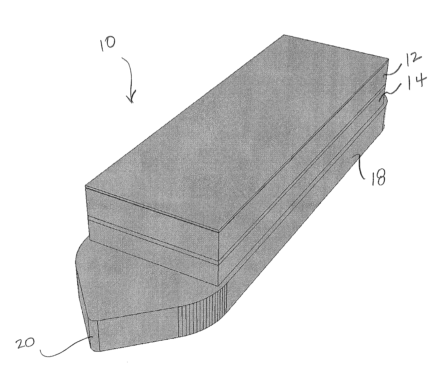
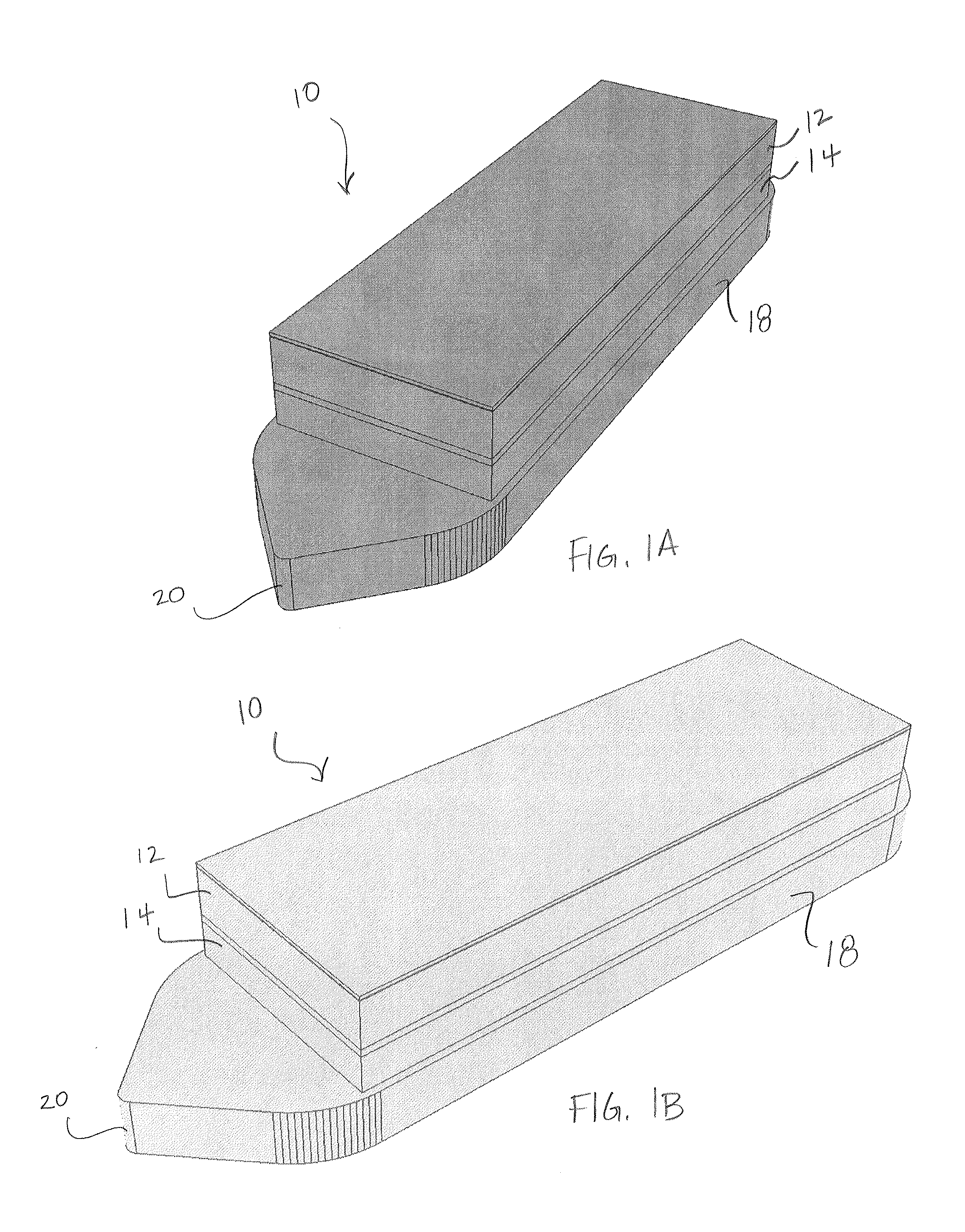
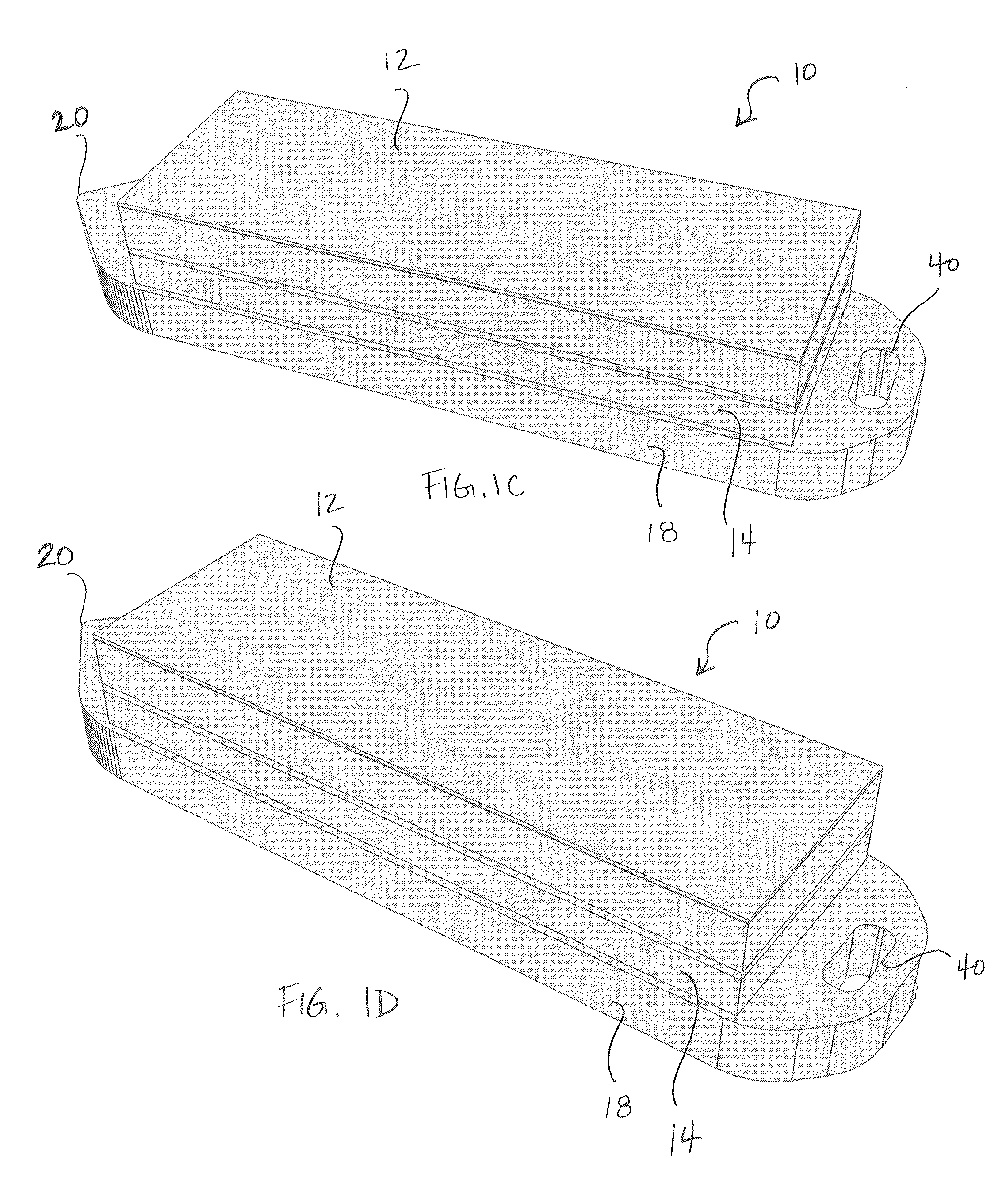
[0044]Embodiments of the present invention provide improved MEMS based pressure sensor implants for accurate and continuous measurement of IOP that can be beneficial in the treatment of eyes, for example beneficial in the treatment of glaucoma. FIGS. 1A and 1B illustrate isometric views of a vertically stacked implantable pressure sensor device 10 for measuring IOP according to embodiments of the present invention. The implantable device 10 comprises vertically stacked heterogeneous components, namely a first MEMS wafer or die 12 and a second CMOS wafer or die 14. The first wafer 12 comprises at least a pressure sensor configured to measure IOP on a frequent or desired basis (e.g., 1 sample per hour, 2-4 samples per day, etc.). The second wafer 14 comprises at least a digitizing ASIC. In some embodiments, the ASIC includes a microcontroller to enable firmware update of the implant, customization of sampling function (rate / window, accuracy, resolution, etc), auto-adaptative sampling ...


PUM


Abstract

The present invention describes vertically stacked and hermetically sealed implantable pressure sensor devices for measuring a physiological signal. The implantable device comprises multiple layers, including a first wafer having a pressure sensor configured to measure the physiological signal and a second wafer having at least a digitizing integrated circuit. The first wafer is vertically stacked or disposed over the second wafer so as to form a hermetic seal. The device may include one or more additional layers adapted for energy storage and transfer, such as a third layer having a super-capacitor and a fourth layer having a thin film battery.

Description

CROSS-REFERENCES TO RELATED APPLICATIONS[0001]The present application is a Non-Provisional of and claims the benefit of priority of U.S. Provisional Application No. 62 / 019,841 filed on Jul. 1, 2014, the entire of contents of which are incorporated herein by reference.[0002]The present application is related to co-assigned and concurrently filed U.S. Non-Provisional patent application Ser. No. ______(Attorney Docket No. 96933-000110US) entitled “Ultra-Miniature Injectable Intra-Ocular Pressure Sensor”; and U.S. Non-Provisional patent application Ser. No. ______(Attorney Docket No. 96933-000310US) entitled “Ultra Low Power Charging Implant Sensors With Wireless Interface for Patient Monitoring”; each of which is incorporated herein by reference in its entirety for all purposes.BACKGROUND OF THE INVENTION[0003]Glaucoma is associated with elevated levels of intraocular pressure (IOP) and can permanently damage vision in the affected eye(s) and lead to irreversible blindness if left untr...

Claims


Application Information

Patent Timeline
Patent Type & Authority Applications(United States)
IPC IPC(8): A61B5/03A61B3/16A61B5/00A61B5/0215A61B5/07A61B17/34A61F9/00
CPCA61B5/036A61B5/686A61B17/3468A61B3/16A61B5/0215A61B2562/12A61B5/076A61F9/0017A61B2560/0214A61B2560/0475A61B2562/0247A61B5/031
Inventor CAO, ARIEL
Owner INJECTSENSE INC
Why Eureka
Try Eureka