Impact Mass Flow Sensor For Monitoring Peanut Harvest Yields

a mass flow sensor and monitoring technology, applied in the direction of liquid/fluent solid measurement, instruments, agriculture tools and machines, etc., can solve the problems of poor in-load resolution relative to yield monitoring technologies available, system cannot be adapted for production use, and cannot quantify whether what is working or not working. to achieve the effect of improving correlation

Active Publication Date: 2016-01-14
CLEMSON UNIV RES FOUND +1
View PDF14 Cites 16 Cited by
  • Summary
  • Abstract
  • Description
  • Claims
  • Application Information

AI Technical Summary

Benefits of technology

[0010]Other components can optionally be included in the yield monitoring system such as optical sensors, air pressure sensors that can monitor pressure within the pneumatic conveyance...

Problems solved by technology

Producers are already using zone management in peanut harvesting but unfortunately have no way of quantifying whether what they are doing is working or is not working: they have no report card.
Unfortunately, while the PYMS demonstrated good ability to predict load and field weight, its in-load resolution was poor relative to yield monitoring technologies available for grains and cotton.
While this system could not be adapted for use by a producer, it was reported to have the potential to more than double harvestable plots per clock hour and triple plot...

Method used


Image

  • Impact Mass Flow Sensor For Monitoring Peanut Harvest Yields
  • Impact Mass Flow Sensor For Monitoring Peanut Harvest Yields
  • Impact Mass Flow Sensor For Monitoring Peanut Harvest Yields

Examples


example 1

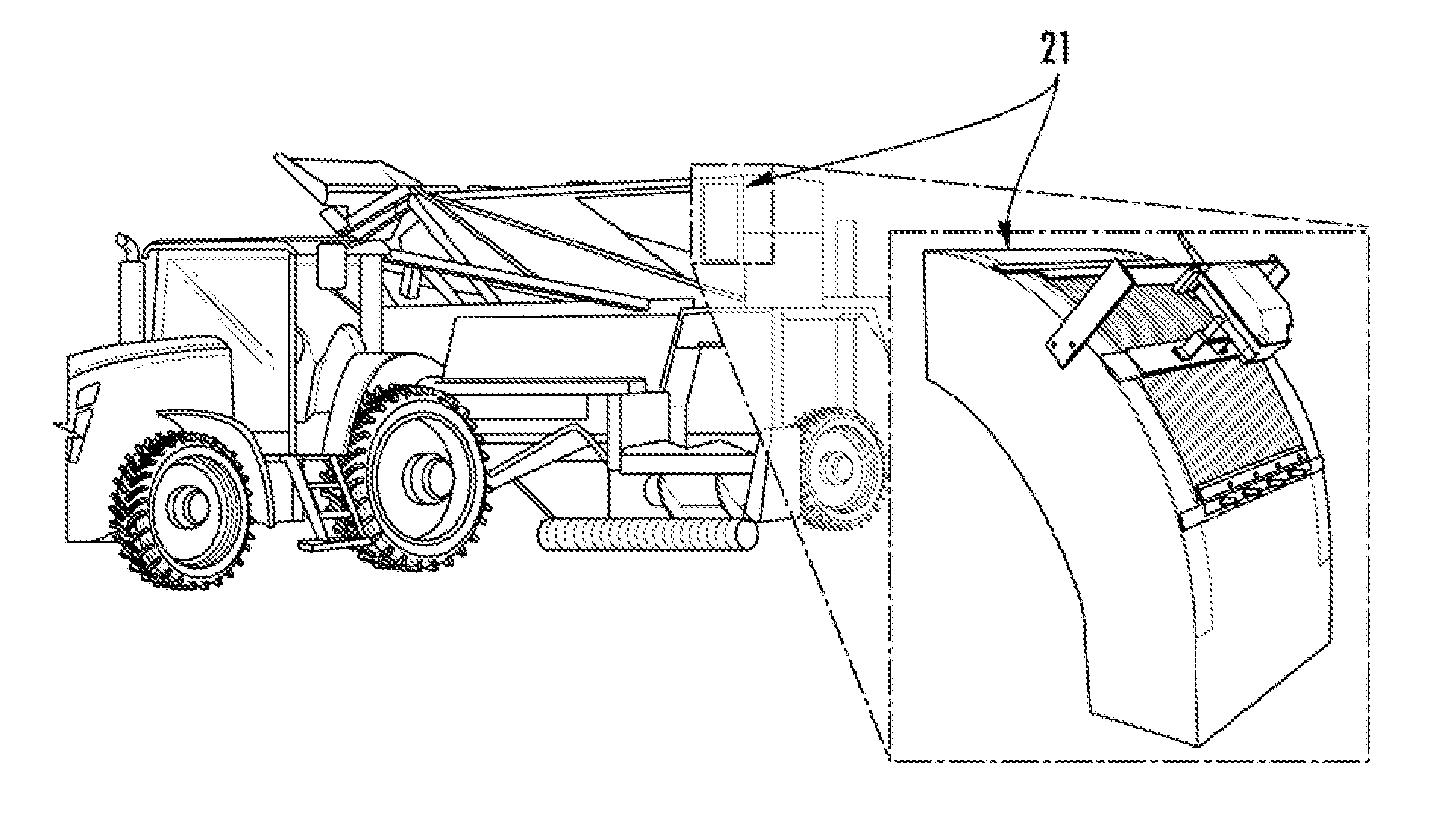
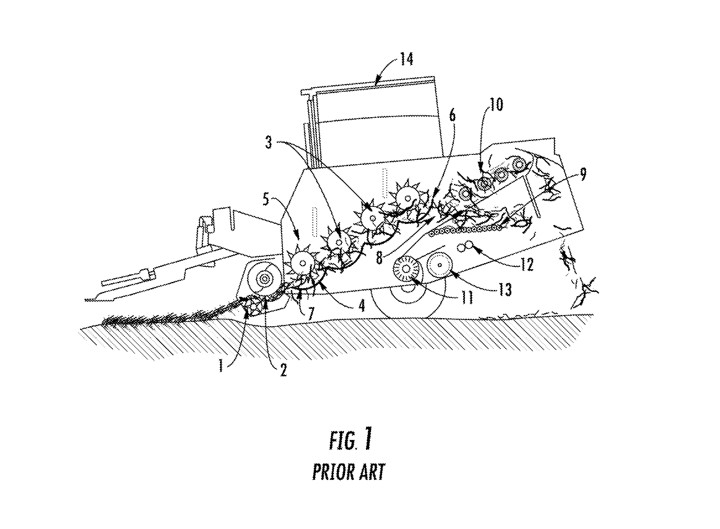
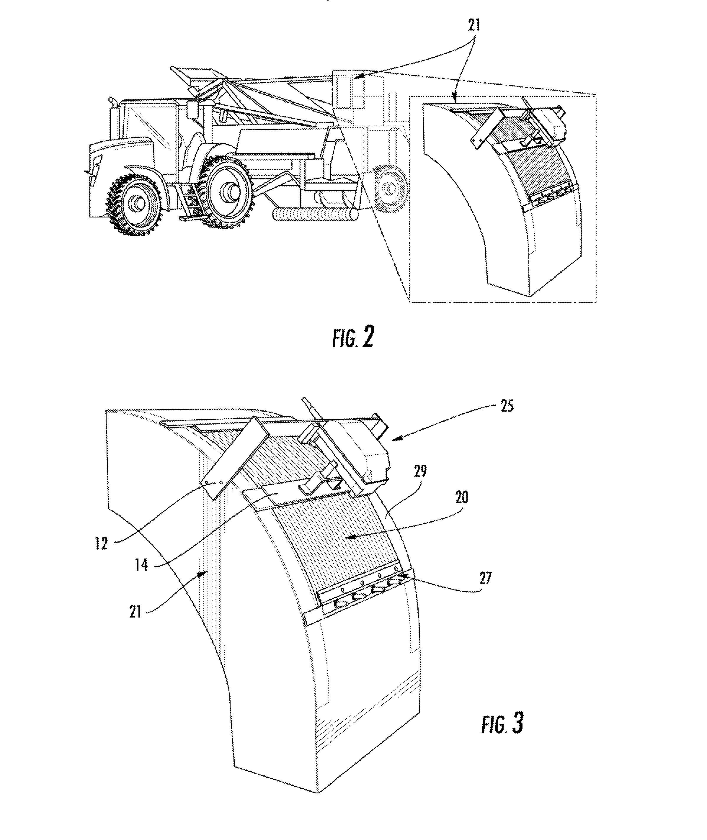
[0083]An Ag Leader® 4000201 (Ag Leader® Technology, Ames, Iowa) impact or “grain” sensor connected to an Ag Leader® Integra monitor was adapted to a four row Bush Hog 9004 (Bigham Brothers, Inc., Lubbock, Tex.) pull-type peanut combine. The load cell of the impact monitor was attached to the exterior of the topmost portion of the clean peanut delivery chute of the combine. The impact plate monitor was located outside of a 90° bend where the peanuts are deflected into the hopper basket as shown in FIG. 2. The impact plate was removed from the bend and the load cell was removed from the sheet metal housing used for mounting in a grain combine. The load cell was fixed to a “floating” section of bar screen on the delivery chute and to the side walls of the peanut basket via a mounting bracket as depicted in FIG. 3. The bar screen was fixed to the chute along its lower (upstream) edge by a piano hinge to restrict motion when peanuts were being deflected into the hopper basket. Installati...

example 2

[0101]An Ag Leader® 4000201 (Ag Leader® Technology, Ames, Iowa) impact plate was mounted on an Amadas 2108 pull type peanut combine and an Ag Leader® Integra monitor was paired with this sensor. Installation and setup for this system was similar to that described Example 1 and shown in FIG. 2. Two configurations of the bar screen attached to the impact plate sensor were employed: one where the bar screen was allowed to float in its position with no hinge (FIG. 8) and one where the piano hinge position was moved to the downstream side of the airflow (FIG. 6), opposite that shown in FIG. 5. In the configuration including the hinge, the bar screen was made to overlap on the outside of the duct on the upstream side of the airflow. The bar screen was not allowed to touch the sides of the duct in either configuration, providing 0.64 cm (0.25 in) or less clearance on all sides, except where the hinge was mounted. Also, the shaft speed sensor that was already installed on the peanut combine...

example 3

[0109]Two combines were set up in the same manner with the same components. A series TDH30 pressure transducer (Transducers Direct, Cincinnati, Ohio) was fitted on the hydraulic circuit of the offloading cylinders on Amadas 2108 and 2110 peanut combines (FIG. 20A), indicating hydraulic pressure in the cap ends of the two parallel cylinders that tilt the basket for dumping the load to a wagon, trailer, or dump cart. The pressure transducers were calibrated against a model AFC-5M-25 pressure gauge (DiscountHydraulicHose.com, Philadelphia, Pa.) as shown in FIG. 21A using pressure generated from a model 60726 portable hydraulic power kit (Harbor Freight Tools Co., Camarillo, Calif.).

[0110]Model AH226124 rotary potentiometer assemblies (Deere & Company, Moline, Ill.) were attached between the supporting frames and the baskets of the peanut combines (FIG. 20B). The rotary potentiometers were calibrated against basket angle relative to the combines (FIG. 21B) using a model 95998 magnetic d...


PUM


Abstract

Yield monitoring systems for harvesting machines and methods that can provide yield monitoring of crops are described. Machines include those that pneumatically convey crop through the machine such as peanut harvesting machines. The yield monitoring system includes a force sensor that can be located in conjunction with a duct of the harvesting machine such that impact of the crop materials on an impact plate within the duct will be registered by the force sensor. This registration can be used to determine a mass flow rate for the crop, which can be correlated to yield of the crop. The systems can include additional components such as optical monitors, moisture sensors, and pressure sensors.

Description

CROSS REFERENCE TO RELATED APPLICATION[0001]This application claims filing benefit of U.S. Provisional Patent Application Ser. No. 62 / 023,275 having a filing date of Jul. 11, 2014, which is incorporated herein by reference.BACKGROUND OF THE INVENTION[0002]As the need for agricultural efficiency and productivity continues to increase, producers must find ways to maximize their crop's potential. Economic drivers arise from increases in fertilizer and herbicide cost, and environmental sanctions call for better pesticide management. Precision agriculture concepts and methods are showing great promise in meeting the world's needs for efficient agricultural practices and are becoming a staple in most row crop producers' management strategies. For instance, cotton and corn producers are using yield monitors to define and assess different zones of production and are managing these zones with variable rate application of inputs. Application of yield monitoring technologies to the production ...

Claims


Application Information

Patent Timeline
IPC IPC(8): G01F1/30A01D29/00A01D33/00
CPCG01F1/30A01D2033/005A01D33/00A01D29/00A01D41/1272
Inventor KIRK, KENDALL R.WHITE, J. WARRENMONFORT, W. SCOTTMASSEY, HUNTER F.FREE, D. HOLLENSBRANTLEY, STANLEY A.PEELE, JOEL S.FRAVEL, JACOB B.HENDERSON, JR., WILLIAM G.
Owner CLEMSON UNIV RES FOUND
Why Eureka
Try Eureka