APPARATUS FOR MANUFACTURING Si-BASED NANO-PARTICLES USING PLASMA

Inactive Publication Date: 2016-01-21
KOREA INST OF ENERGY RES
View PDF2 Cites 2 Cited by
  • Summary
  • Abstract
  • Description
  • Claims
  • Application Information

AI Technical Summary

Benefits of technology

The present invention relates to a method for producing Si nanoparticles and Si-C composites with controlled characteristics based on process conditions such as plasma power, gas type, flow rate, and cooling gas. The method does not require a vacuum, reducing equipment costs. The invention also involves concentrating the plasma on the reactor center to protect the outer wall and prevent contamination. The use of SiOx nanoparticles produced by the method as a negative electrode active material for a lithium secondary battery provides excellent capacity retention rate.

Problems solved by technology

In particular, nano-sized silicon is one of the solutions to mitigate a large volume expansion (300 to 400%) of a silicon-based negative electrode occurring during charging and discharging of the battery, which causes a reduced service life.
However, sufficient buffering effect on the volume changes that occur during charging and discharging of the battery with nano-sized silicon alone cannot be obtained.

Method used


Image

  • APPARATUS FOR MANUFACTURING Si-BASED NANO-PARTICLES USING PLASMA
  • APPARATUS FOR MANUFACTURING Si-BASED NANO-PARTICLES USING PLASMA
  • APPARATUS FOR MANUFACTURING Si-BASED NANO-PARTICLES USING PLASMA

Examples


first embodiment

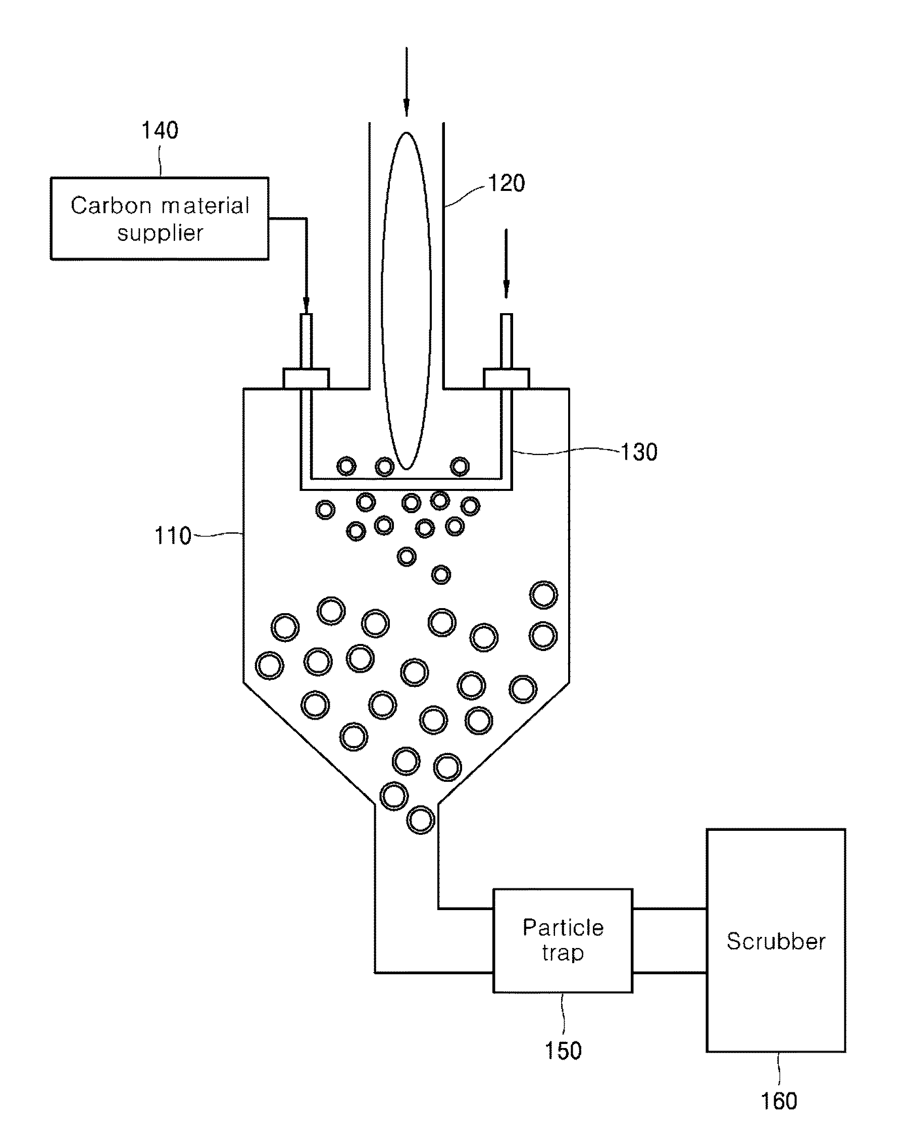
[0055]FIG. 1 is a conceptual view showing an apparatus for manufacturing silicon-based nanoparticles according to the present disclosure, more specifically, shows an apparatus capable of producing Si—C composite nanoparticles.

[0056]As depicted, an apparatus for manufacturing Si—C composite according to the present disclosure includes a reaction chamber 110 for providing a reaction space, a plasma torch 120 for generating plasma to decompose silicon precursors and produce Si particles, a cooling part 130 for cooling the Si particles supplied thereto, provided within the reaction chamber 110, and a carbon material supplying part 140 for supplying carbonaceous materials into the reaction chamber 110.

[0057]The plasma torch 120 is provided on an upper portion of the reaction chamber 110, and the cooling part 130 is provided on a lower portion of the plasma torch 120.

[0058]Carbon material supplying part 140 is connected to the cooling part 130, and therefore carbonaceous materials can be ...

second embodiment

[0089]FIG. 9 is a conceptual diagram showing an apparatus for manufacturing silicon-based nanoparticles according to the present disclosure, and, more specifically, shows an apparatus capable of producing SiOx nanoparticles.

[0090]The apparatus of manufacturing silicon-based nanoparticles depicted in FIG. 9 is similar to that depicted in FIG. 1 as a whole. However, the apparatus depicted in FIG. 9 is further provided with a swirl gas inlet 124.

[0091]As depicted, the apparatus for manufacturing SiOx nanoparticles according to an embodiment of the present disclosure includes a reaction chamber 110 for providing a reaction space, a microwave plasma torch 120 for generating plasma using a microwave to decompose silicon precursors and produce Si particles, and a cooling part 130 for cooling SiOx nanoparticles so formed, provided within the reaction chamber 110.

[0092]The plasma torch 120 is provided on an upper portion of the reaction chamber 110, comprising a precursor gas inlet 122 and a...


PUM


Abstract

Disclosed herein is an apparatus for manufacturing silicon-based nanoparticles such as Si—C composite and SiOx using plasmas. An apparatus for manufacturing silicon-based nanoparticles in accordance with one embodiment of the present disclosure comprises a reaction chamber for providing a reaction space; a plasma torch for generating plasma to decompose silicon (Si) precursors and produce Si particles, provided on an upper portion of the reaction chamber; a cooling part for cooling Si particles supplied into the reaction chamber, provided within the reaction chamber; and a carbon material supplying part for supplying carbonaceous materials or carbon precursors into the reaction chamber.

Description

CROSS-REFERENCE TO RELATED APPLICATION[0001]This application claims the benefit of Korean Patent Applications No. 10-2014-0090084 and No. 10-2014-0090085, filed on Jul. 16, 2014 in the Korean Intellectual Property Office, the disclosure of which is incorporated herein in its entirety by reference.BACKGROUND[0002]1. Technical Field[0003]The present disclosure relates to an apparatus for manufacturing Si-based nanoparticles such as Si—C composite and SiOx using plasma.[0004]2. Description of the Related Art[0005]Silicon nano-powders are known as materials widely applicable to various advanced electronic or optical fields. For example, in printable electronics, a nano-ink composition comprising silicon nano-powders is used in environmentally friendly process for forming a semiconductor layer for electrical or optical function. Recently, many studies have been made on silicon having a high theoretical capacity as a negative electrode active material for a high capacity lithium-ion batte...

Claims


Application Information

Patent Timeline
IPC IPC(8): B01J19/08B01J19/12
CPCB01J19/088B01J19/126B01J2219/0805B01J2219/0871B01J2219/1206B01J2219/0875B01J2219/0877B01J2219/0879B01J2219/0869B01J2219/0801B01J2219/0809B01J2219/0816B01J2219/0822B01J2219/0839B01J2219/089B01J2219/0894C01B33/027C01B33/113C01B32/05
Inventor JANG, BO-YUNLEE, JIN-SEOKKIM, JOON-SOOKOO, JEONG-BOON
Owner KOREA INST OF ENERGY RES
Why Eureka
Try Eureka