Unlock instant, AI-driven research and patent intelligence for your innovation.

Curved bullet proof glass made of glass, glass-ceramic or ceramic mechanically curved on the strike-face layer

a technology of glass and ceramics, applied in glass tempering equipment, manufacturing tools, transportation and packaging, etc., can solve the problems of limited transparency of ceramic materials, insufficient use of ceramic materials in designing and manufacturing bullet-proof glass, and inability to manufacture bullet-proof composites

Active Publication Date: 2016-01-28
AGP AMERICA
View PDF6 Cites 1 Cited by
  • Summary
  • Abstract
  • Description
  • Claims
  • Application Information

AI Technical Summary

Benefits of technology

This approach enables the production of curved bullet-proof composites with improved flexibility and mechanical resistance, reducing production time and costs while avoiding the risks of ruptures and optical defects, and achieving weight and thickness reductions while meeting ballistic performance standards.

Problems solved by technology

However, ceramic materials are not massively used in designing and manufacturing bullet-proof glass due to the high cost of these materials in comparison to Soda-Lime glass, Borosilicate glass and glass-ceramics, as set forth in patent application US2010 / 0275767.
Transparency of these materials is limited.
Two of the top disadvantages of transparent ceramic materials which can be included in bullet-proof composites are their high cost and restricted availability of large sizes (areas less than 0.5 m2).
However, the cost of Borosilicate glass is greater than the cost of Soda-Lime glass.
Likewise, no evidence is found in prior art of curved ballistic composites with multi-layers wherein ceramic materials are used in the strike-face layer (1) and in the intermediate layers (2).
The greatest disadvantage of painting the perimeter black stripe in bullet-proof composite using glass enamels is the loss of mechanical resistance in glass when painted using this type of paint.
When the glass or glass-ceramic layers have spaces like those mentioned above (3.1 mm), the risk of a rupture increases when undergoing pressure and temperature lamination because glass and glass-ceramics are fragile materials which do not have a high degree of deformation.
Another possible defect generated due to the lack of parallelism between layers is optical distortion (magnifying effect) generated when the spaces formed between glass layers curved by gravity and temperature are sufficiently small for glass layers not to break during lamination but instead generate the mentioned optical distortion, which is an undesired defect in bullet-proof composites for automobile applications.
When glass or glass-ceramics break due to an excessively fast volume change, this is known as material failure due to thermal shock.
If a given material is rapidly cooled but not sufficiently fast so as to cause rupture thereof, said material accumulates internal stresses because the molecules do not reach thermodynamic equilibrium.
Said simultaneous bending-annealing process of layers is not recommended for materials whose softening temperatures are different since this reduces optic quality of materials by increasing the presence of markers having lesser softening temperatures, reduces bending process optimization since there is a need to wait for materials having greater softening temperature to acquire the final shape of the piece, and also, the risk of spacing between layers increases.
On the other hand, the simultaneous bending-annealing of glass layers requires a slow cooling system (<10° C. / minute) in order for the hot interfaces (contacting glass or glass-ceramic internal surfaces) to cool at rates similar to the cooling rate of the surfaces in contact with air; these temperature differences between glass / glass, glass / air, glass-ceramic / glass or glass-ceramic / air interfaces may cause undesirable internal tensions which also lead to ruptures.
In view of the above, it can be noted that prior art does not provide any information regarding the flexibility that ion exchange renders materials, and the way this property can be used in order for said materials to be mechanically curved during pressure and temperature lamination.
In addition, prior art also does not disclose that composites in which one type of material is used in the strike-face layer (1) and a different material is used in the intermediate layers (2), are not destined to be used in curved bullet-proof composites.
Finally, prior art also does not consider the possibility of carrying out individual bending of the intermediate layers (2) by means of a semi-tempered or heat strengthened bending process instead of an annealing-bending process.

Method used


Image

  • Curved bullet proof glass made of glass, glass-ceramic or ceramic mechanically curved on the strike-face layer
  • Curved bullet proof glass made of glass, glass-ceramic or ceramic mechanically curved on the strike-face layer
  • Curved bullet proof glass made of glass, glass-ceramic or ceramic mechanically curved on the strike-face layer

Examples


example 1

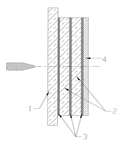
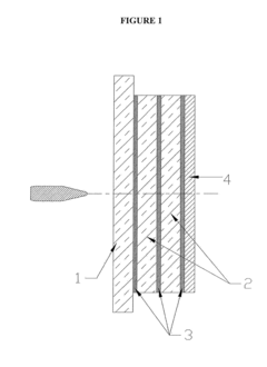
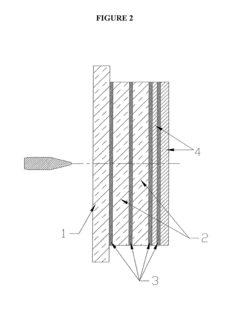
[0081]FIG. 7a illustrates a composite which uses Alkali Aluminosilicate (SAS), Lithium Aluminosilicate (LAS) or Soda-Lime having a thickness ranging between 2 and 3 mm with ion exchange in the strike-face layer (10) mechanically curved during the heat and pressure lamination process, a borosilicate glass layer having a thickness ranging between 9 and 13 mm in the intermediate layers (20) without ion exchange and curved / semi-tempered or heat strengthened by means of gravity and temperature, a polycarbonate layer having a thickness ranging between 1 and 3 mm in the internal plastic layer (40) and polyurethane adhesive layers (30) with a thickness ranging from 0.3 to 3.1 mm. The described composite complies with requirements set forth in NIJ 0108.01 for level III A with a thickness ranging from 14 to 17 mm; the standard formula used to comply with level III A requirements of the same norm has a thickness of 21 mm and therefore, thickness and weight reduction can range between 19 and 33...

example 2

[0082]FIG. 7a illustrates a composite which uses Alkali Aluminosilicate (SAS), Lithium Aluminosilicate (LAS) or Soda-Lime having a thickness ranging between 2 and 3 mm with ion exchange in the strike-face layer (10), a Soda-Lime glass layer having a thickness ranging between 8 and 14 mm in the intermediate layers (20) with ion exchange and curved / semi-tempered or heat strengthened by means of gravity and temperature, a polycarbonate layer having a thickness ranging between 1 and 3 mm in the internal plastic layer (40) and polyurethane adhesive layers (30) with a thickness ranging from 0.3 to 3.1 mm. The described composite complies with requirements set forth in NIJ 0108.01 for level III A with a thickness ranging from 14 to 18 mm; the standard formula used to comply with level III A requirements of the same norm has a thickness of 21 mm and therefore, thickness and weight reduction can range between 0 and 30%.

example 3

[0083]FIG. 7b illustrates a composite which uses Alkali Aluminosilicate (SAS), Lithium Aluminosilicate (LAS) or Soda-Lime having a thickness ranging between 2 and 3 mm with ion exchange in the strike-face layer (10), two layers of borosilicate glass having a thickness ranging between 5 and 13 mm in the intermediate layers (20) without ion exchange and curved / semi-tempered or heat strengthened by means of gravity and temperature, a polycarbonate layer having a thickness ranging between 1 and 6 mm in the internal plastic layer (40) and polyurethane adhesive layers (30) with a thickness ranging from 0.3 to 3.1 mm. The described composite complies with requirements set forth in NIJ 0108.01 exceeding level III A and offers thickness and weight reduction ranging between 20 and 35%.


PUM

PropertyMeasurementUnit
areasaaaaaaaaaa
densityaaaaaaaaaa
curvature radiusaaaaaaaaaa

Abstract

A curved bullet-proof composite comprising:a glass or glass-ceramic external strike-face layer having been subjected to an ion exchange process and which is mechanically curved; at least one glass or glass-ceramic intermediate layer; an internal plastic layer; and an adhesive material between the strike-face layer, the at least one intermediate layer and the internal plastic layer.

Description

1. FIELD OF THE INVENTION[0001]The present invention is related to the manufacture of curved bullet-proof composites which incorporate glass, glass-ceramics or transparent ceramics on the strike-face layer, wherein the curvature of the materials used on the strike-face layer is obtained mechanically during the pressure and temperature (heat) lamination process.2. DESCRIPTION OF THE ART[0002]A conventional bullet-proof composite is comprised of a set of different Soda-Lime1 layers, which are found bound together by layers of adhesives which generally are polymers, and in general have a polycarbonate layer on the inside part of the composite.[0003]Making reference to FIG. 1, the architecture of a bullet-proof composite commonly found in the art is shown. Starting from outside to inside (“outside” meaning the space from where a bullet is normally shot from; likewise, “inside” refers to the space protected by the bullet-proof composite), an strike-face glass layer (1) which receives the...

Claims


Application Information

Patent Timeline
Patent Type & Authority Applications(United States)
IPC IPC(8): C03B23/025
CPCC03B23/0258C03B23/0256B32B17/10064B32B17/10137F41H5/0407Y10T428/26Y10T428/24959Y10T156/1002
Inventor MANNHEIM ASTETE, MARIO ARTURO BENJAMINSUAREZ CUERVO, JUAN PABLOBENITEZ PALMETH, JUVENAL TOBIASESPINOSA ROJAS, JUAN CARLOSMONTANO FORERO, MARIA CAROLINA
Owner AGP AMERICA