Cooling device for internal combustion engine provided with blowby gas recirculation device and turbocharger (as amended)

Inactive Publication Date: 2016-01-28
TOYOTA JIDOSHA KK
View PDF9 Cites 6 Cited by
  • Summary
  • Abstract
  • Description
  • Claims
  • Application Information

AI Technical Summary

Benefits of technology

The present invention relates to a cooling device for an internal combustion engine with a blowby gas recirculation device and a turbocharger. The cooling device has two separate cooling systems: one for cooling the engine body and the other for cooling the intake air. The second cooling system cools the compressor of the turbocharger. The cooling abilities of both systems can be set independently, allowing for optimal cooling of both the engine and the compressor. The second cooling system uses a single cooling medium to cool both the intake air and the compressor. The intake air is cooled when it is at a low temperature, which helps to improve engine performance. The cooling of the intake air is stopped when the engine is at a low temperature to facilitate warming of the engine. The cooling medium is maintained at a high temperature to prevent the formation of condensed water and to suppress the generation of condensed water when exhaust gas is introduced into the intake passage. The cooling device allows for optimal cooling of the engine and the turbocharger with a simple control system.

Problems solved by technology

Therefore, the oil mist flowing into the compressor is subject to the high temperature.
Such an accumulation of the deposits reduces a supercharging efficient of the turbocharger.

Method used


Image

  • Cooling device for internal combustion engine provided with blowby gas recirculation device and turbocharger (as amended)
  • Cooling device for internal combustion engine provided with blowby gas recirculation device and turbocharger (as amended)
  • Cooling device for internal combustion engine provided with blowby gas recirculation device and turbocharger (as amended)

Examples


first embodiment

Effect derived

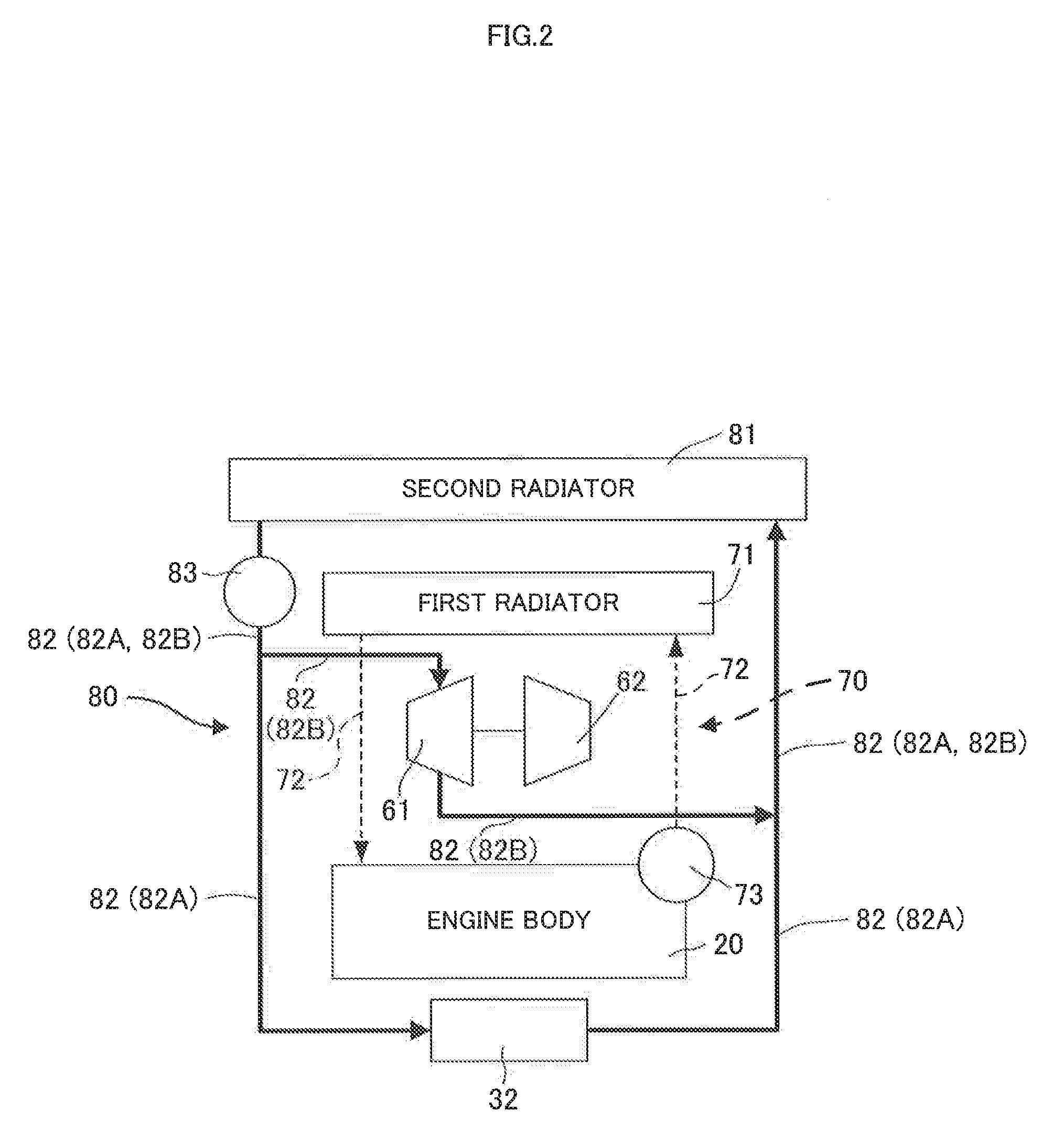
[0046]According to the first embodiment, the first and second cooling devices 70 and 80 are provided, separately and thus, the cooling abilities of the first and second cooling devices 70 and 80 can be separately set, respectively. In addition, the cooling ability of the first cooling device 70 is set to an ability for accomplishing the required engine cooling degree and the cooing ability of the second cooling device 80 is set to an ability for accomplishing the required compressor cooling degree. Therefore, both of the required engine and compressor cooling degrees can be accomplished.

Second Embodiment

[0047]A second embodiment will be described. The engine provided with a cooling device according to the second embodiment corresponds to the engine shown in FIG. 1. The cooling device according to the second embodiment corresponds to the cooling device shown in FIG. 3. The first cooling device 70 according to the second embodiment is the same as the first cooling device...

second embodiment

Effect derive

[0049]An effect derive from the second embodiment will be described. The required compressor cooling degree may be smaller than the required intake air cooling degree. Even in this case, according to the second embodiment, both of the required compressor and intake air cooling degrees can be exactly accomplished.

Third Embodiment

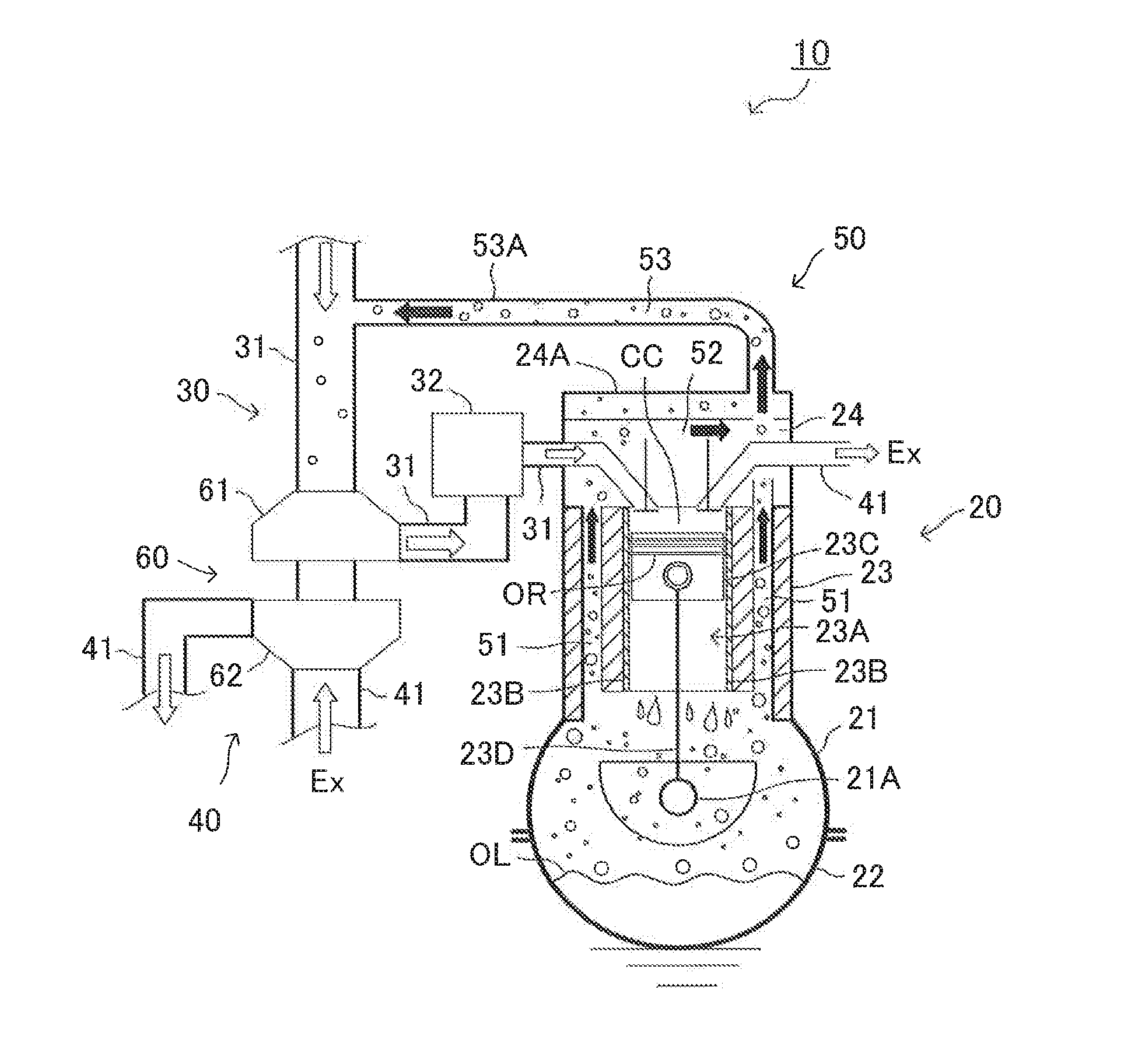
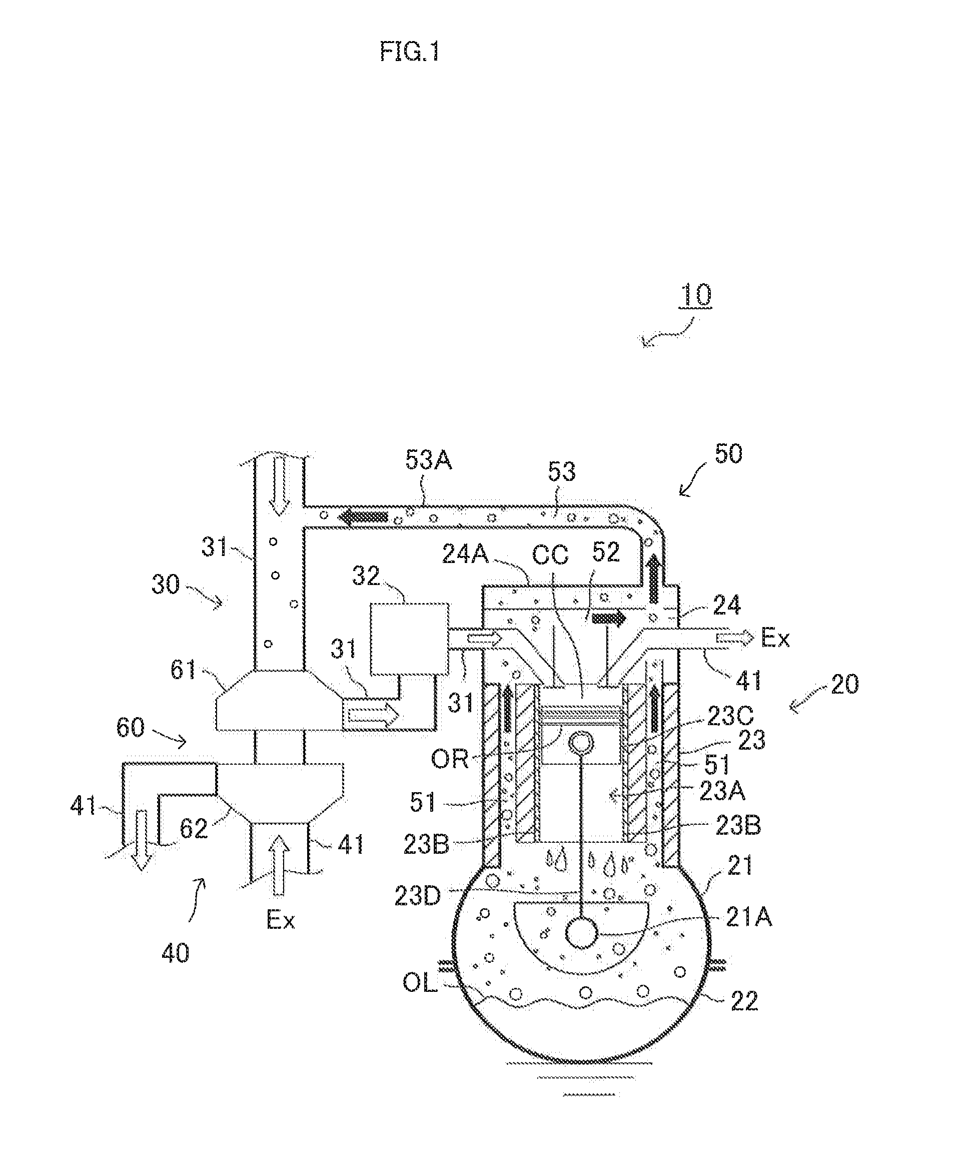
[0050]A third embodiment will be described. The engine provided with a cooling device according to the third embodiment corresponds to the engine shown in FIG. 1. The cooling device according to the third embodiment corresponds to the cooling device shown in FIG. 2. The second cooling device 80 according to the third embodiment is the same as the second cooling device 80 according to the first embodiment except that the cross-sectional flow area of the cooling water passage 82B passing the compressor 61 is smaller than the cross-sectional flow area of the cooing water passage 82A passing the intercooler 32.

[0051]Note that the cooling ability of t...

third embodiment

Effect derived

[0052]An effect derived from the third embodiment will be described. The required compressor cooling degree may be smaller than the required intake air cooling degree. Even in this case, according to the third embodiment, both of the required compressor and intake air cooling degrees can be exactly accomplished.

Fourth Embodiment

[0053]A fourth embodiment will be described. The engine provided with a cooling device according to the fourth embodiment corresponds to the engine shown in FIG. 1. The cooling device according to the fourth embodiment corresponds to the cooling device shown in FIG. 4. The first cooling device 70 according to the fourth embodiment is the same as the first cooling device 70 according to the second embodiment. The second cooling device 80 according to the fourth embodiment is the same as the second cooling device 80 according to the second embodiment except that the second cooling device 80 according to the fourth embodiment has a compressor bypas...


PUM


Abstract

The object of the invention is to provide a cooling device for accomplishing both of required engine and compressor cooling degrees. The invention relates to a cooling device for an engine provided with a blowby gas recirculation device (50) and a turbocharger (60), the blowby gas recirculation device recirculating a blowby gas to an intake passage upstream of a compressor of the turbocharger. The cooling device comprises a first cooling device (70) for cooling a body (20) of the engine and a second cooling device (80) for cooling an intake air, separately. The second cooling device cools the compressor (61).

Description

FIELD OF THE INVENTION[0001]The present invention relates to a cooling device for an internal combustion engine provided with a blowby gas recirculation device and a turbocharger.BACKGROUND ART[0002]There is known a system for ventilating a crank case by recirculating to an intake passage, a blowby gas leaking from combustion chambers of an internal combustion engine (hereinafter, will be referred to as “the engine”) to the crank case. This system is also referred to as a blowby gas recirculation device or a PCV (a Positive Crank case Ventilation).[0003]An oil may be spattered in the crank case due to rotation of a crank shaft at a high speed and blowoff of an in-cylinder gas from between a piston ring and an inner peripheral wall surface defining a cylinder bore and the like. As a result, an oil mist (that is, liquid particles of lubrication oil) is generated in the crank case. In case that the engine has a turbocharger, when the oil mist is recirculated to the intake passage toget...

Claims


Application Information

Patent Timeline
IPC IPC(8): F02M35/10F01M13/00F01P11/04F02B29/04F02B37/00F02B39/00F02B39/16
CPCF02M35/10222F02B37/00F01M13/00F02B29/0443F01P11/04F01M2013/0038F02M35/10157F02B39/005F02B39/16F02B2039/164F02M25/0709F02M25/06F01M13/021F01M2013/027F02B37/005F02M26/06Y02T10/12
Inventor SHIOTA, JUMPEISUGIYAMA, MATSUYOSHIYOEDA, KEIJIYAMANE, NARUTOSUGIYAMA, SATOSHIMATSUMOTO, ISAOTABATA, MASAKAZU
Owner TOYOTA JIDOSHA KK
Why Eureka
Try Eureka