Oil Supply Device

Active Publication Date: 2016-01-28
HITACHI ASTEMO LTD
View PDF3 Cites 8 Cited by
  • Summary
  • Abstract
  • Description
  • Claims
  • Application Information

AI Technical Summary

Benefits of technology

[0016]According to the present invention, since one oil pump is selectively driven by a driving motor and a motor, the number of parts for the oil pump decreases while an existing function is secured, and simplification of a confi

Problems solved by technology

If the transmission enters a neutral state, engagement of the transmission is generated when the oil pressure is increased by actuation of the engine, and vibration occurs due to a difference of rot

Method used


Image

  • Oil Supply Device
  • Oil Supply Device
  • Oil Supply Device

Examples


first embodiment

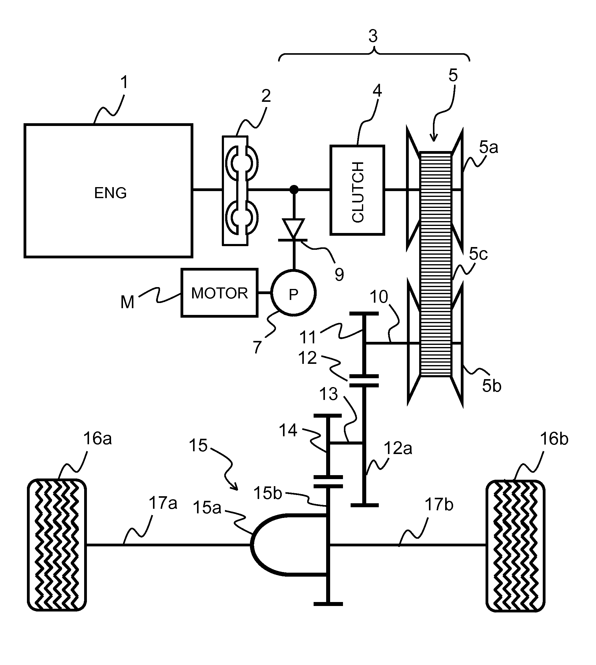
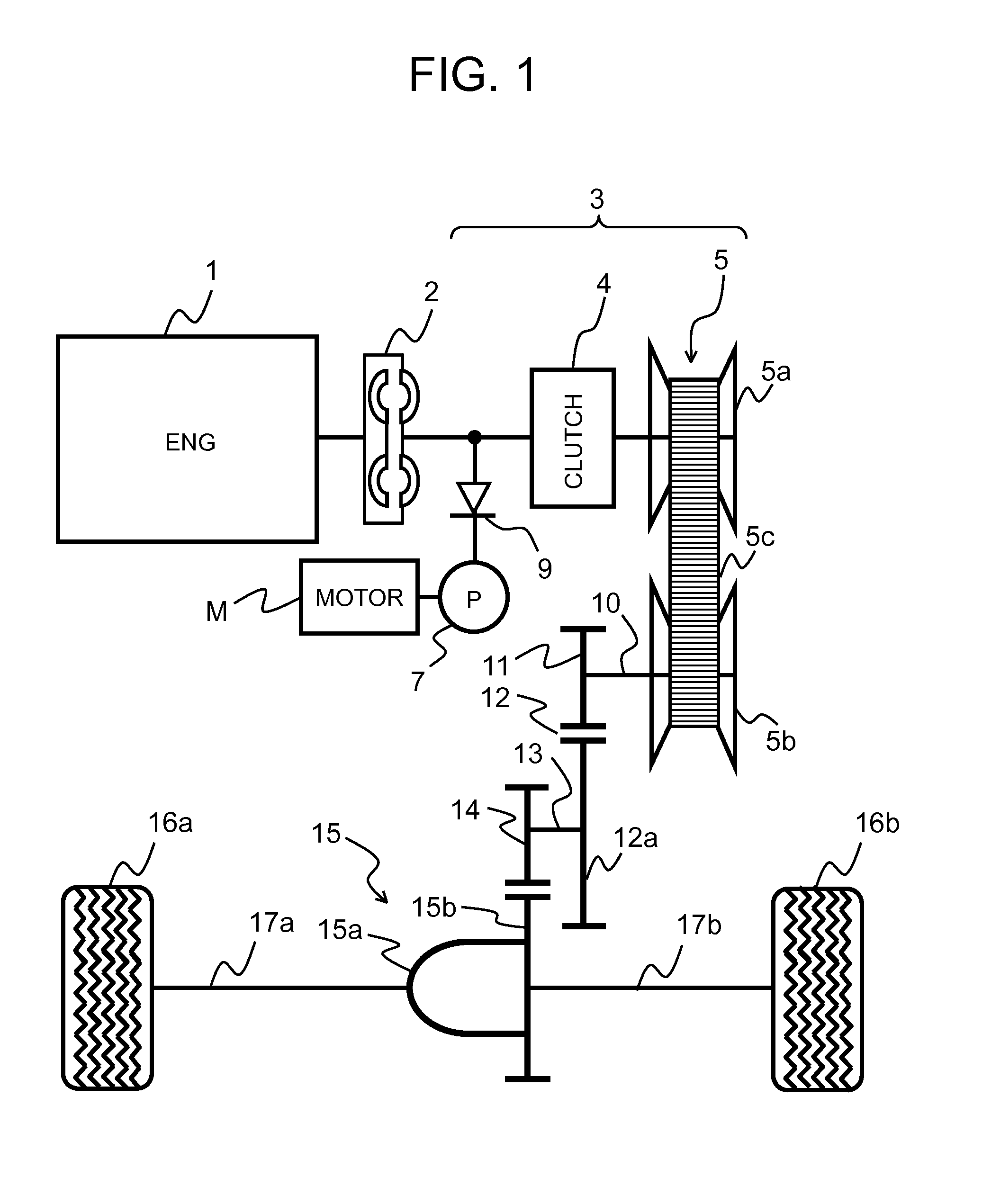
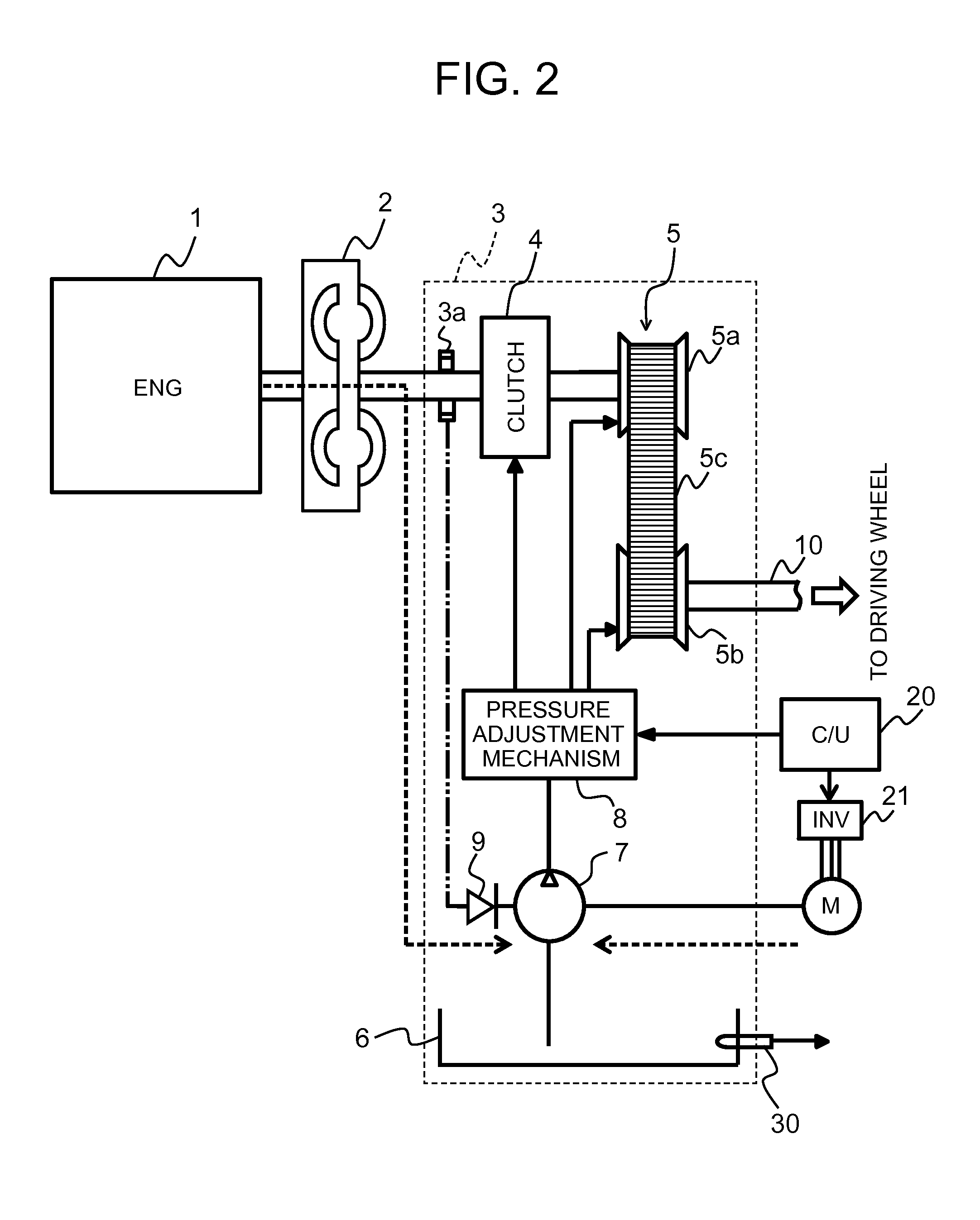
[0033]FIG. 1 illustrates an oil supply device according to a first embodiment of the present invention, and is a schematic view when a driving motor of a vehicle is an engine (internal combustion engine) and the oil supply device is applied to an automatic transmission of the engine. In addition, FIG. 2 is a view illustrating a main portion, which is extracted from the oil supply device illustrated in FIG. 1, in detail.

[0034]An engine (ENG) 1 which is a power source of a vehicle has an idle reduction function, and engine 1 is automatically stopped by stopping a fuel supply to engine 1 at a predetermined idle reduction condition. Thereafter, the fuel supply to engine 1 restarts when an idle reduction discontinuing condition is satisfied, and engine 1 is actuated.

[0035]An output shaft of engine 1 is connected to a transmission (automatic transmission) 3 via a torque converter 2. Transmission 3 is configured so as to include a clutch 4, a continuously variable transmission 5, an oil pu...

example 1

[0058]FIG. 5 is a diagram for explaining an operation pattern for each traveling scene. In addition, FIG. 6 is a timing chart illustrating a relationship between a vehicle speed, an engine speed, a motor rotating speed, and a pump rotating speed, and a motor operation and a traveling scene in the operation pattern illustrated in FIG. 5. In the present Example 1, motor M is driven according to a driving condition of a vehicle.

[0059]Here, a series of operations is illustrated in which after a vehicle starts from an engine stop state, departs, is accelerated, and reaches a normal traveling state, the vehicle is decelerated and stopped (with coasting reduction or idle reduction), and the vehicle is restarted. In addition, it is assumed that there is a margin for the power of a battery, and not only is an oil pressure maintained at the time of coasting reduction or idle reduction, but also engine 1 is assisted by motor M in an idling state, a start state, and an acceleration state.

[0060]...

example 2

[0074]FIG. 7 is a diagram for explaining another operation pattern for each traveling scene, and motor M is driven according to a driving condition of a vehicle. In addition, FIG. 8 is a timing chart illustrating a relationship between a vehicle speed, an engine speed, a motor rotating speed, and a pump rotating speed, and a motor operation and a traveling scene in the operation pattern illustrated in FIG. 7. Similar to the above-described Example 1, in the present Example 2, motor M is driven according to a driving condition of a vehicle.

[0075]Here, a series of operation is illustrated in which after a vehicle is started from an engine stop state, departs, is accelerated, and reaches a normal traveling state, the vehicle is decelerated and stopped (with coasting reduction or idle reduction), and the vehicle is restarted. In addition, an oil pressure is maintained at the time of the coasting reduction or the idle reduction, engine 1 is assisted by motor M at the time of starting, id...


PUM


Abstract

The present invention relates to an oil supply device for use in an automatic transmission mounted on a vehicle, and is applied to a vehicle in which an idle reduction control or the like is performed. The oil supply device includes an oil pump which is driven by a driving motor of a vehicle and a motor separate from the driving motor, and an engagement and disengagement element which transmits a driving force of the driving motor to the oil pump, and the oil pump is driven by the motor without using a drive system of the driving motor.

Description

TECHNICAL FIELD[0001]The present invention relates to an oil supply device for use in an automatic transmission which is mounted on a vehicle, for example, and particularly, relates to an oil supply device which is applied to a vehicle in which an idle reduction control or the like is performed.BACKGROUND ART[0002]In order to perform an operation, lubrication, cooling, or the like of an automatic transmission or the like mounted on a vehicle, in general, oil supply (oil-pressure supply) is performed using a hydraulic pump (mechanical oil pump) driven by an internal combustion engine (engine) which is a drive source mounted on the vehicle. The mechanical oil pump is connected to an engine, and specifications (natural discharging amount) of the pump are determined from a maximum flow rate and an engine speed required for a transmission, and are associated with the rotating speed of an engine.[0003]Accordingly, when an idle reduction function or the like is provided on an engine, if th...

Claims


Application Information

Patent Timeline
IPC IPC(8): F16H57/04B60R17/02
CPCF16H57/0436B60R17/02F16H57/0435F16H57/0439F16H61/0028
Inventor MIYAMOTO, SHOGO
Owner HITACHI ASTEMO LTD
Why Eureka
Try Eureka