
Brillouin optical distributed sensing device and method with improved tolerance to sensor failure

a distributed sensing and optical technology, applied in the direction of thermometers, instruments, sensors, etc., can solve the problems of low sensitivity, inability to directly discriminate the effects of temperature and strain, and the beam itself may produce acoustic vibrations in the medium via electrostriction, etc., to achieve easy reconfiguration, avoid excessive complexity and extra cost, and improve sensitivity

Active Publication Date: 2016-01-28
OMNISENS
View PDF17 Cites 23 Cited by
  • Summary
  • Abstract
  • Description
  • Claims
  • Application Information

AI Technical Summary

Benefits of technology

The invention is a system for detecting Brillouin scattering using both stimulated and spontaneous methods. The key advantage is that the system can be easily reconfigured using the spontaneous method when the sensors are damaged. The system is also designed to use the same components for both methods, reducing complexity and cost. Additionally, the invention describes a new way of implementing spontaneous Brillouin scattering, which allows for improved sensitivity by using narrow-bandwidth detection.

Problems solved by technology

In addition, when an intense beam such as a laser beam travels in a medium such as an optical fiber, the variations in the electric field of the beam itself may produce acoustic vibrations in the medium via electrostriction.
The effects of temperature and strain cannot be directly discriminated.
But the sensitivity which may be obtained is low because the spontaneous Brillouin scattering signal is very week.
In addition, the photodetector must have a bandwidth larger that the frequency shift of the Brillouin scattering (>12 GHz), which is not favorable to high sensitivity and low noise.
So in case of breach of the fibers, or even of one of the fibers, measurements are no longer possible.
This is a serious drawback in practice, because the distributed sensors are usually embedded in structures such as pipelines, with no possibility of replacing them once embedded.
In addition they are frequently used in severe environments where the risk to have them subjected locally to excessive strain is high.

Method used


Image

  • Brillouin optical distributed sensing device and method with improved tolerance to sensor failure
  • Brillouin optical distributed sensing device and method with improved tolerance to sensor failure
  • Brillouin optical distributed sensing device and method with improved tolerance to sensor failure

Examples


Embodiment Construction

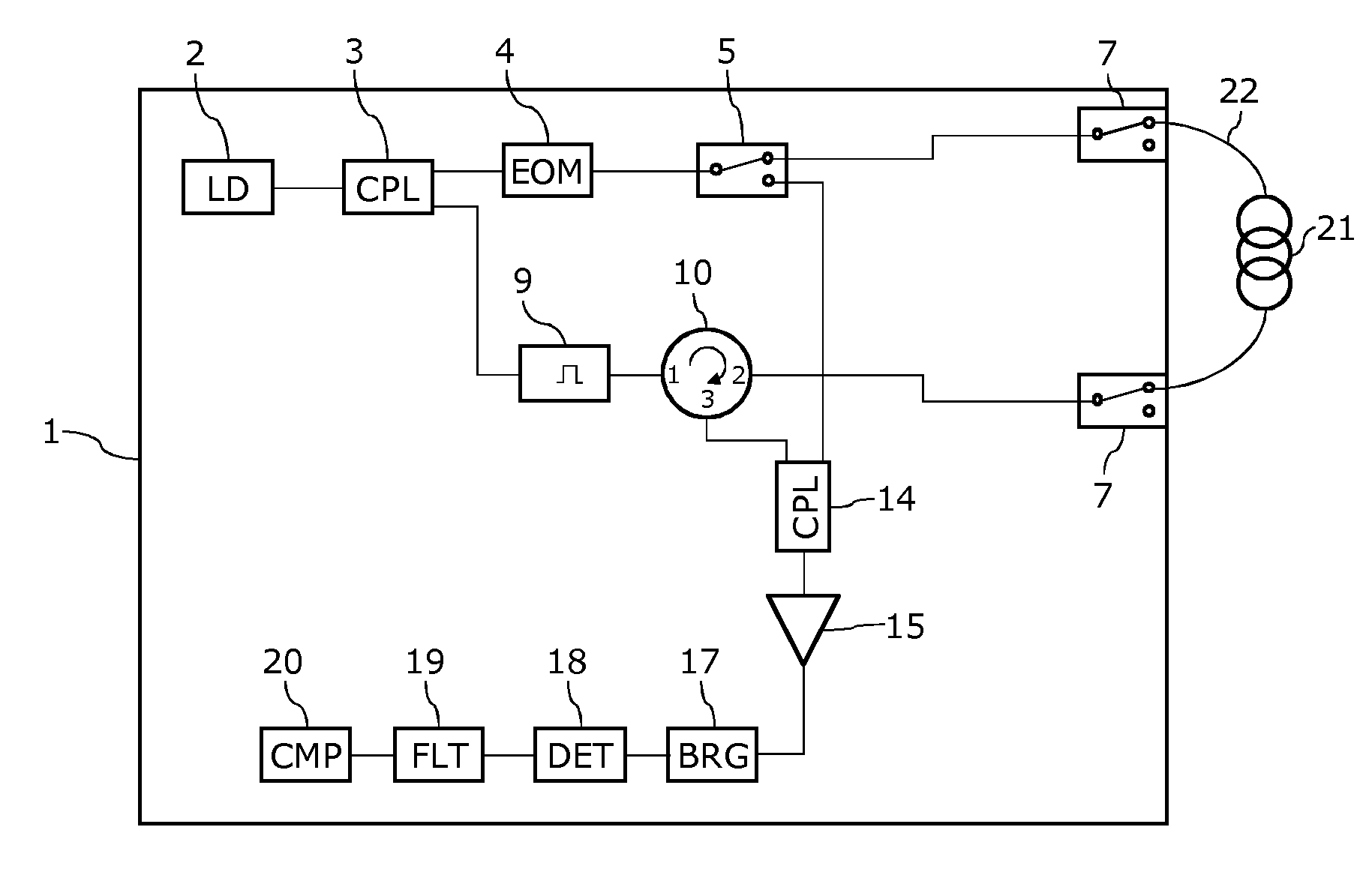
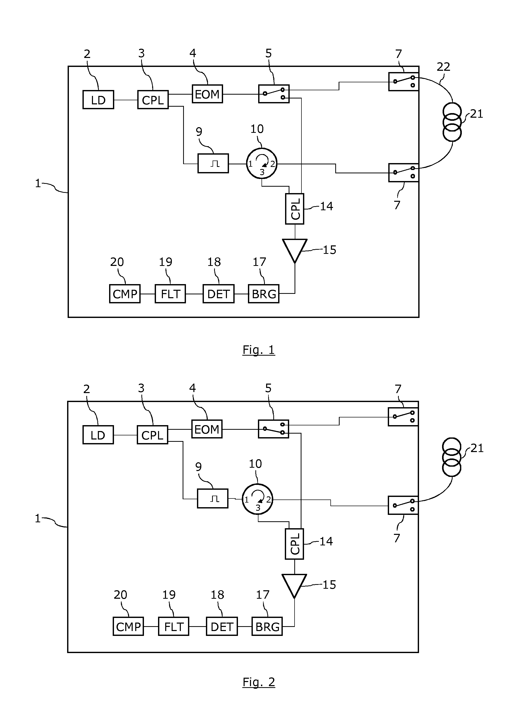
[0124]With reference to FIG. 1 and FIG. 2, we will now describe a mode of realization of a Brillouin optical distributed sensing device of the invention.

[0125]For sake of clarity, only the components which are relevant for the description of the invention are shown on FIG. 1 and FIG. 2. It is obvious that the device of the invention may include any other necessary components.

[0126]In the mode of realization presented on FIG. 1 and FIG. 2, the sensing device of the invention 1 comprises a light source 2 which is used for generating all necessary optical signals. This light source 2 comprises a distributed feedback laser diode (DFB-LD) which generates a continuous wave.

[0127]A source coupler 3 directs a part of the light issued from the source 2 towards a pulse generator 9 for generating an optical pulsed signal.

[0128]The pulse generator 9 comprise a semiconductor optical amplifier (SOA) driven by an electrical pulsed signal. A variable optical attenuator and an erbium-doped fiber amp...


PUM


Abstract

A Brillouin optical distributed sensing device and method includes a structure for generating an optical pulsed signal and an optical probe signal. Includes is a circulation component for directing the optical pulsed signal to a sensing optical fiber and for directing an optical measurement signal with Brillouin scattering information arising from the sensing optical fiber toward a detection apparatus. Also included is an optical routing component for configuring the device to allow generating: (i) according to a first configuration, an optical measurement signal with stimulated Brillouin scattering information resulting from the interaction of the optical pulsed signal, and an optical probe signal propagating in the sensing optical fiber in a direction opposite to the optical pulsed signal, or (ii) according to a second configuration, an optical measurement signal with spontaneous Brillouin scattering information resulting from the propagation of the optical pulsed signal in the sensing optical fiber.

Description

FIELD OF THE INVENTION[0001]The invention relates to a Brillouin optical time domain analyzer device with improved tolerance to degradation and breach of sensing optical fibers.[0002]The field of the invention is, but not limited to, distributed temperature and / or strain sensing using Brillouin scattering.BACKGROUND OF THE INVENTION[0003]The use of Brillouin scattering in optical fibers is a well known technique for doing measurements of temperature and / or strain along large distances.[0004]Brillouin scattering occurs when a light wave propagating in a medium (such as an optical fiber) interacts with time-dependent density variations of the medium. These density variations may be due for instance to acoustic waves or phonons propagating in the medium, and they modulate the index of refraction. A fraction of the light wave interacts with these variations of index of refraction and is scattered accordingly. Since acoustic waves propagates at the speed of sound in the medium, deflected...

Claims


Application Information

Patent Timeline
Patent Type & Authority Applications(United States)
IPC IPC(8): G01D5/353
CPCG01D5/35348G01D5/35364G01K11/32G01L1/242
Inventor NIKLES, MARCROCHAT, ETIENNEBRIFFOD, FABIENMONTAVON, JEAN-CHARLESSANGHOON, CHIN
Owner OMNISENS
Learn More