Prosthetic component with crosslinked polymer wear zone and edge protection

Inactive Publication Date: 2016-02-04
MCMINN DEREK JAMES WALLACE
View PDF3 Cites 2 Cited by
  • Summary
  • Abstract
  • Description
  • Claims
  • Application Information

AI Technical Summary

Benefits of technology

The invention provides a method for making thin prosthetic components that have a full thickness crosslinked wear zone and a non-crosslinked edge, which makes them more resistant to damage through edge loading. The method involves using an antioxidant in a liquid, powder, solution or suspension form, which can be dissolved or mixed into polymer particles. The antioxidant coats the particles and helps prevent damage. This results in a more durable and reliable prosthetic component.

Problems solved by technology

Where a thin crosslinked polyethylene articular layer is provided in an acetabular cup prosthesis (either as a thin homogenous crosslinked layer or alternatively a thin crosslinked surface layer on top of a conventional polyethylene layer, as described above), it has the disadvantage that loads applied to the cup edge can fracture the crosslinked polyethylene layer resulting in increased debris and a high likelihood of pain and further complications.
However, in this case, the weak crosslinked polyethylene layer has the additional disadvantage that failure can occur at a locking mechanism provided between the crosslinked polyethylene layer and a metal tibial base plate and fracture of associated stabilising pegs can also occur.
Shoulder and other implants (e.g. dual mobility hip bearings) including crosslinked polyethylene layers have similar disadvantages of vulnerability to edge loading fracture and / or failure at locking mechanisms.

Method used


Image

  • Prosthetic component with crosslinked polymer wear zone and edge protection
  • Prosthetic component with crosslinked polymer wear zone and edge protection
  • Prosthetic component with crosslinked polymer wear zone and edge protection

Examples


first embodiment

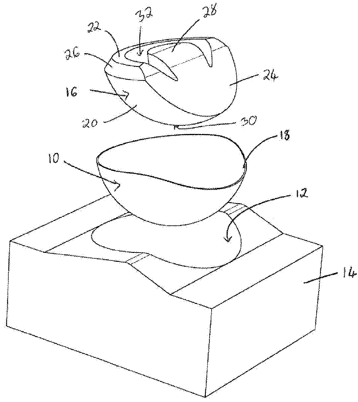
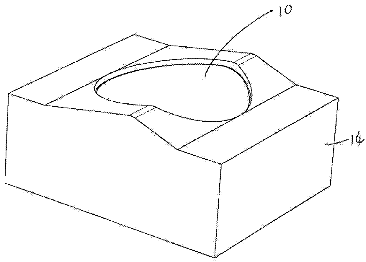
[0063]FIGS. 1 to 3 illustrate the initial steps in a method for manufacturing a prosthetic component in the form of an acetabular cup for use in hip resurfacing, in accordance with the invention. In this embodiment, the method comprises positioning a metal cup 10 within a part-sperical recess 12 in a mould base 14 and locating a crosslinked polymer preform 16 in the metal cup 10.

[0064]The metal cup 10 is formed of porous titanium (although in other embodiments titanium alloy, tantalum or cobalt chromium alloys may be employed), is substantially hemi-spherical and includes an anterior-inferior cut-out 18.

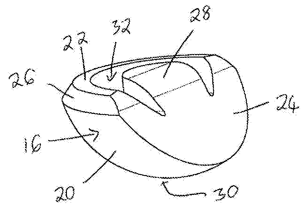
[0065]The prefrom 16 is formed from polyethylene powder which has been blended with vitamin E, consolidated and radiation crosslinked. The prefrom 16 comprises a part-spherical external surface 20 terminating at an upper superior edge 22 and a lower inferior edge 24. The superior edge 22 includes a bevel 26 to increase the surface area for attachment to non-crosslinked polymer, as wi...

second embodiment

[0071]FIGS. 7 and 8 illustrate a method for manufacturing a prosthetic component in the form of a dual mobility hip component, in accordance with the invention. In this embodiment, the method is similar to that described above but no metal components are required. In this instance, a mould base 50 is provided which includes a short cylindrical recess 52 extending vertically downwardly from the centre of a hemi-spherical recess 54. A crosslinked preform 56 having a complementary cylindrical locating spigot 58 depending from a solid part-spherical body 60 is then located in the mould base 50. The spigot 58 is provided to prevent the preform 56 from tilting when non-crosslinked polymer powder is poured on top prior to moulding. As above, the prefrom 56 is formed from polyethylene powder which has been blended with vitamin E, consolidated and radiation crosslinked. An upper horizontal surface 62 of the body 60 is substantially flat in the centre but has a digitated edge 64.

[0072]Non-cro...

third embodiment

[0075]FIGS. 9 to 11 illustrate a method for manufacturing a prosthetic component in the form of a uni-compartmental tibial component for a knee (UKR), in accordance with the invention. In this embodiment, the method comprises positioning a porous metal base plate 88 having a planar upper surface 90 and two hollow legs 92 depending (at an angle front-to-back) therefrom in mould base 94 having complementary recesses. A crosslinked polymer preform 96 comprising a solid complementary body 98 with depending legs 100 is then located on the metal base plate 88. The prefrom 96 (including vitamin E) is sized so as to leave an edge of the metal base plate 88 exposed. In addition, a lowermost corner of the body 98 is provided with a bevel 101 to increase the space available for accommodating non-crosslinked polymer 102 at the edge.

[0076]The non-crosslinked polymer powder 102 (preferably also including vitamin E) is then placed around and on top of the preform 96 to completely fill the exposed ...


PUM

PropertyMeasurementUnit
Timeaaaaaaaaaa
Thicknessaaaaaaaaaa

Abstract

A method of manufacturing a prosthetic component comprises providing crosslinked polymer in a mould and moulding non-crosslinked polymer to a free edge of the crosslinked polymer to form a hybrid component. A portion of the crosslinked polymer and a portion of the non-crosslinked polymer is then removed so as to form a prosthetic component having a full thickness crosslinked wear zone and at least one non-crosslinked edge.

Description

FIELD OF THE INVENTION[0001]The present invention relates to prosthetic component with a crosslinked polymer wear zone and edge protection. In particular embodiments, the prosthetic component may constitute the whole or a part of a prosthesis, for example, an acetabular cup prosthesis for use in hip resurfacing or a tibial component for use in a knee replacement procedure.BACKGROUND TO THE INVENTION[0002]It is known to use a metal acetabular cup with a separate crosslinked polymer inner liner in a hip replacement or resurfacing procedure. It is also known to direct compression mould non-crosslinked polymer power to a metal cup shell to create a monoblock component and then to crosslink the polymer portion by radiation.[0003]Due to its superior wear properties when compared to conventional polyethylene, it has further been proposed to use a thin layer of crosslinked polyethylene to form an articular bearing surface of a prosthetic component and to leave a bulk layer behind the crossl...

Claims


Application Information

Patent Timeline
IPC IPC(8): A61F2/30A61F2/34A61F2/38B29B11/14B29C43/18
CPCA61F2/3094A61F2/389A61F2/34A61F2/3877B29C43/183B29B11/14B29L2031/7532B29K2105/24B29K2105/253B29K2705/08B29K2623/10B29K2995/0078B29K2023/06A61F2002/30016A61F2002/3208B29C49/071B29C2949/0715A61F2002/30026A61F2002/30004
Inventor MCMINN, DEREK, JAMES, WALLACE
Owner MCMINN DEREK JAMES WALLACE
Why Eureka
Try Eureka