Thermoformed Structural Composites

a structural element and composite technology, applied in the field of thermoformed structural elements and composites, can solve the problems of two or more plastics to undergo mixing or blending, the plastics used in the recycling process are not compatible with each other, and the major unresolved challenges of recycling mixed plastics and mixed plastics with non-plastic contaminants, so as to eliminate the eliminate the cost of direct labor costs, and eliminate the effect of cost and loss of time valu

Active Publication Date: 2016-02-04
ECOSTRATE SFS INC +2
View PDF2 Cites 5 Cited by
  • Summary
  • Abstract
  • Description
  • Claims
  • Application Information

AI Technical Summary

Benefits of technology

[0048]The end products can have the same outward appearance as those products made by the more demanding, more expensive extrusion process and or injection process but the present invention's end products can be pre-engineered to have significantly, unexpectedly, improved physical and chemical properties.
[0050]Another object of the present invention is the elimination of costs and loss of time-value associated with separation of waste-stream plastics into thermoplastics, thermosets, and non-plastics and then the elimination and loss of time-value of conversion of such materials into film and or sheet and or plate before such materials enter a thermoforming process.
[0051]An object, in reference with the previous paragraphs, of the present invention is to eliminate the direct labor costs associated with ‘grinding’ plastic material, to such a condition, in preparation to pelletizing said plastic material, so as to feed said pelletized plastic material before extruding plastic material into sheet, thereby readying said plastic sheet material for shearing and or cutting such, before placement of cut plastic sheet material in a thermoform.
[0052]Another object, in reference with the previous paragraphs, of the present invention is to eliminate the direct labor costs associated with pelletizing said plastic material, so as to feed said pelletized plastic material before extruding plastic material into sheet, thereby readying said plastic sheet material for shearing and or cutting such, before placement of cut plastic sheet material in a thermoform.
[0053]Yet another object, in reference with the previous paragraphs, of the present invention is to eliminate the direct labor costs associated with extruding plastic material into sheet, thereby readying said plastic sheet material for shearing and or cutting such, before placement of cut plastic sheet material in a thermoform.
[0055]A further object of the present invention is to ease and encourage the use of post-consumer plastics in thermoform operations. By eliminating the need to pelletize and or sheet-extrude plastic material(s) before thermoforming, the significant costs, involved in ‘separation’ and or ‘cleaning’ post-consumer plastic material, are eliminated.

Problems solved by technology

There is a major unresolved challenge in recycling mixed plastics and mixed plastics with non-plastic-contaminates.
The difficulty with this type of recycling process is that the different plastics used in the recycling process are not compatible with each other.
There is an inherent inability of two or more plastics to undergo mixing or blending, which means that some plastics cannot be mixed together during the recycling process.
Even a small amount of the wrong type of plastic can ruin an entire container or bale of recycled material.
Mixed or co-mingled plastics are frequently contaminated with such items as metals, paper, pigments, inks, adhesives, carbon fiber, flame retardants, fiber reinforced plastics, glass filled plastics, cured silicon and rubber.
Thermosets cannot be re-melted or remolded and therefore have been traditionally difficult to recycle.
In general, polymers cannot be homogeneously mixed with one another, and even attempting to mix most polymers will result in phase-separated mixtures.
Polystyrene is generally a stiff, brittle, material that will break or shatter if bent.
Examples of problems in recycling plastics include cases where a quantity of recycled PET is contaminated with a small amount of PVC.
In the reverse, where a small amount of PET contaminates recycled PVC, the PET will remain in solid form after the PVC reaches its melting point, which results in crystalline PET inhabiting the post-melt-cooled PVC structure.
A major problem in the recycling of PVC is its high chlorine content of raw PVC, and the hazardous additives added to the polymer to achieve the desired material quality.
PVC recycling is difficult because of high separation and collection costs, loss of material quality after recycling, and the low market price of recycled PVC compared to virgin PVC.
Plastics not identified by code numbers are difficult to recycle.
These items, such as computer keyboards, do not fit into the numbering system that identifies plastics used in consumer containers.
In particular, the initial curvature of fibers causes fiber buckling, which reduces the stiffness of the composite.
It also gives rise to transverse tensions, which may promote delamination failure.”
Also, Urquhart & O'Rourke state that “[w]ithin the limit of elasticity the hooped reinforcement is much less effective than longitudinal reinforcement, Such reinforcement, however, raises the ultimate strength of the column, because the hooping delays ultimate failure .
. . plastic lumber made from HDPE, PVC, PP, or virgin resins has been characterized as having insufficient stiffness to allow its use in structural load-bearing applications.”“For example, it is noted that non-reinforced plastic lumber products typically have a flexural modulus of only one-tenth to one-fifth that of wood such as Douglas fir, .
However, none of the prior art known to applicant is capable of fabricating plastic lumber having the structural stiffness and strength of products made according to the present invention .
Also, “[t]he addition of wood particles to plastic also results in some undesirable characteristics.
For example, wood particles may rot and are susceptible to fungal attack, wood particles can absorb moisture, wood particles are on the surface of a WPC member can be destroyed by freeze and thaw cycling, wood particles are susceptible to absorbing environmental staining, e.g., from tree leaves, wood particles can create pockets if improperly distributed in a WPC material, which may result in a failure risk that cannot be detected by visual inspection, and wood particles create manufacturing difficulties in maintaining consistent colors because of the variety of wood species color absorption is not consistent.
As a result, the wood particles on the surface tend to undergo environmental bleaching.
Consequently, repairing a deck is difficult due to color variation after 6 months to a year of sun exposure.”
Problems associated with typical preformed core materials include difficulties associated with incorporating the materials into the extrusion process due to the pre-formed shape of the materials.”
Therefore increasing strength by fiber orientation is not applicable to an extrusion process.”
However structural mechanical properties of the foam core tend not to be addressed.
“One problem that may occur when a core material and a structural material are not compatible both chemically and physically is delamination.
Chemical and physical incompatibility can result in composite structures that suffer structural failures when the core material and the structural material separate from one another.”
“Although a core material and a structural material may be initially combined into a composite member without regard to the CTE's of each, this does not guarantee structural integrity over time.
For example, thermal plastics are stronger at colder temperatures but are more brittle.
Selecting appropriate materials for a composite is complicated because composites are not homogeneous materials.

Method used


Image

  • Thermoformed Structural Composites
  • Thermoformed Structural Composites
  • Thermoformed Structural Composites

Examples


Embodiment Construction

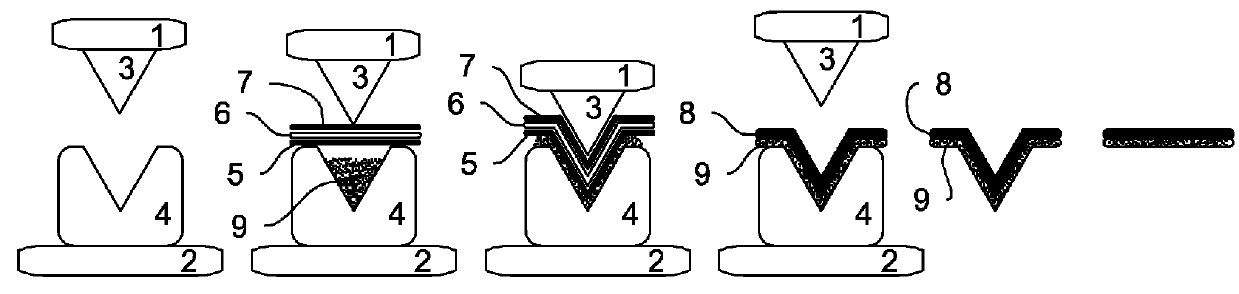
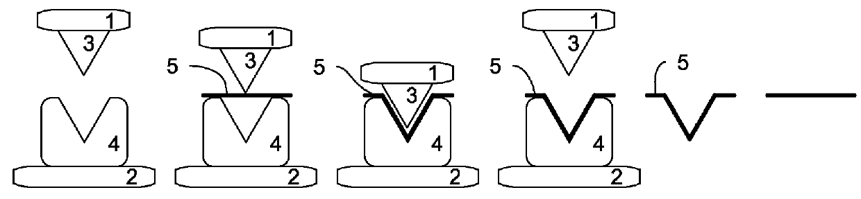
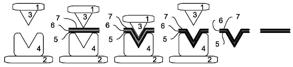
[0079]The invention utilizes the manufacturing process known as ‘thermoforming’. The thermoform process combines thermally charging a material, usually a material such as plastic sheet, to a pliable or plastic-state, and pressing, frequently via a vacuum, into a desired shape. The thermoformed item is usually then allowed to cool resulting in a hardening of the thermoformed material. Thermoforming is frequently the lowest-cost-manufacturing process, over other processes, due in part to usually lower tooling costs and greater factory flexibility.

[0080]Thermoform methods and systems are usually subdivided, denoted, as “thin-gauge” and “thick-gauge”. By industry standard, thin-gauge methods and systems usually mean a finished product that is 1.5 mm (0.059 in.) or less in thickness. Thick-gauge methods and systems usually mean a finished product which is 3 mm (0.12 in.) or greater in thickness.

[0081]The present invention is applicable regardless of the final thermoformed product's thick...


PUM

PropertyMeasurementUnit
thermal massaaaaaaaaaa
thermal energy densityaaaaaaaaaa
thermal-energy gradientaaaaaaaaaa

Abstract

The present invention is generally directed to methods and systems for making thermoformed structural elements and composites, including the use of composites, dissimilar or variable processing materials. The present invention avoids the expense and the technical issues of the present art on how difficult it is to ‘clean’ said ‘dirty’ recycled materials so that they are acceptable to the extrusion process and or the injection mold process. The end products can have the same outward appearance as those products made by the more demanding, more expensive extrusion process and or injection process, but the present invention's end products can be pre-engineered to have significantly, unexpectedly, improved physical and chemical properties.

Description

RELATED U.S. APPLICATION DATA[0001]This application is a divisional of patent application Ser. No. 13 / 839,018, filed on Mar. 15, 2013, entitled “Thermoformed Structural Composites”, the entire disclosure of which is incorporated herein by reference.TECHNICAL FIELD OF THE INVENTION[0002]The present invention is generally directed to methods and systems for making thermoformed structural elements and composites, including the use of composites, dissimilar or variable processing materials.BACKGROUND OF THE INVENTION[0003]There is a major unresolved challenge in recycling mixed plastics and mixed plastics with non-plastic-contaminates. The difficulty with this type of recycling process is that the different plastics used in the recycling process are not compatible with each other. There is an inherent inability of two or more plastics to undergo mixing or blending, which means that some plastics cannot be mixed together during the recycling process. Also, different types of plastics are...

Claims


Application Information

Patent Timeline
Patent Type & Authority Applications(United States)
IPC IPC(8): C08L77/00B29C51/02C08L25/06C08L55/02C08L67/03
CPCC08L77/00C08L55/02C08L25/06C08L67/03B29K2105/16C08L2205/03C08L2207/20B29K2101/12B29K2105/26B29C51/02B29B17/0042B29C51/002B29C51/082Y02W30/62C08L101/00C08L33/20
Inventor SHERGA, RONALD, MATTHEW
Owner ECOSTRATE SFS INC
Why Eureka
Try Eureka