Conical devices for three-dimensional aggregate(s) of eukaryotic cells

Inactive Publication Date: 2016-02-04
INNOVATIVE SURFACE TECHNOLOGIES LLC
View PDF3 Cites 8 Cited by
  • Summary
  • Abstract
  • Description
  • Claims
  • Application Information

AI Technical Summary

Benefits of technology

[0022]This disclosure offers several benefits that can contribute to its ease of use. Unlike the Hanging Drop Method, the cell culture-containing drops are not easily dislodged by, for example, vibration or movement of the cell culture plate. Even if violent vibration (e.g., dropping of the cell culture plate) were to cause the drops located in conical device(s) to fall down through the viewing aperture, the cell aggregate(s) growing in each drop could easily be recovered from the bottom of each well in the well plate that is positioned directly below each device. In addition, replenishment of the medium bathing the 3D cell aggregate(s) can be performed easily by removing some of the used cell medium that surrounds the cell aggregate(s) in small aliquots and replacing it with fresh cell medium. This medium replacement can also be streamlined by employing automated dispensing devices for high throughput applications.
[0023]Addi

Problems solved by technology

In the last decade, various studies have demonstrated that in vitro 2D cell monolayers do not accurately represent the in vivo microenvironment, nutrient intake, or biochemical processes including protein production.
However, producing a product that facilitates the formation of 3D cell aggregate(s) has proven to be a difficult design challenge.
This makes it harder to control the culture environment and determine the effects of exogenous factors.
However, there are multiple drawbacks to the Hanging Drop Method.
For example, the drops of medium are held on the surface of the Petri dish only by surface tension and adhesion forces, resulting in drop size being limited to a volume of 50 μL or less to resist the gravitational force pulling down on each drop.
A further drawback to this method is that the drops are accessible only if the Petri dish lid containing the drops is gently inverted.
Thus, it becomes difficult to conveniently change the medium surrounding the cells and to periodically observe the growth of the cell aggregate(s) u

Method used


Image

  • Conical devices for three-dimensional aggregate(s) of eukaryotic cells
  • Conical devices for three-dimensional aggregate(s) of eukaryotic cells
  • Conical devices for three-dimensional aggregate(s) of eukaryotic cells

Examples


example 1

[0100]White HIPS coupons were coated with two different polymers, both with and without the presence of nanoparticles to evaluate water contact angles. Two coupons were coated with polyisobutylene (PIB): one coupon, “PIB-coated,” was coated with a 10 mg / mL PIB (90:10 mixture of Aldrich PIB Mw 50 K:BASF Oppanol B PIB, Mw 4 million, available from Aldrich, Milwaukee, Wis.; and BASF Corporation, Wilmington, Del., respectively) solution in n-hexane, and the other coupon, “PIB / Tex1-coated,” was coated with a dispersion in n-hexane of 10 mg / mL PIB (90:10 mixture of Aldrich PIB Mw 50K:BASF Oppanol B PIB, Mw 4 million, available from Aldrich, Milwaukee, Wis.; and BASF Corporation, Wilmington, Del., respectively) and 12 mg / mL CABOT CAB-O-SIL™ TS-530 fumed silica nanoparticles (Cabot Corporation, Boston, Mass.). Two other coupons were coated with hydrophobic fluorinated copolymer: one coupon, “F8H2A-coated,” was coated with a 10 mg / mL fluorinated copolymer (1H,1H,2H,2H-perfluorodecyl acrylate...

example 2

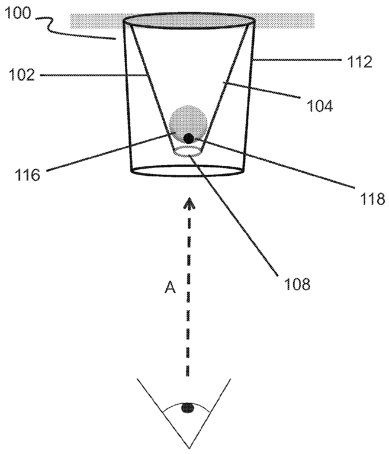
[0104]Conical devices having similar dimensions to the conical device illustrated in FIG. 4 were vacuum formed and used in order to determine whether the position of an aqueous drop inside a conical device would be located at a suitable focal distance when examined by an inverted microscope to ensure proper viewing of the drop and its contents for cell culture experiments and for taking digitized microscope images (LEICA™ DM IL LED microscope, used with a LEICA™ DFC 400 12V, 200 mA digitizer and LEICA™ Application Suite software; available from Leica Microsystems, Buffalo Grove, Ill.).

[0105]Three conical devices were singly cut out of the molded 0.5-mm-thick molded white HIPS sheet in order to individually fit into the wells of a commercially available 96-well cell culture plate. Each device was used as a separate experiment. Conical devices were cleaned and subsequently coated using the previously described protocols at the beginning of the “EXAMPLES” section.

[0106]FIG. 5 illustrat...

example 3

[0108]Three textured hydrophobic conical devices having similar dimensions to the conical device illustrated in FIG. 4 were evaluated for utility and non-cytotoxicity in monitoring the growth of 3D eukaryotic cell aggregate(s) in drops containing eukaryotic cells suspended in culture medium. Bovine aortic endothelial (BAEC) cells were used in this experiment.

[0109]Conical devices were cleaned and subsequently coated using the previously described protocols at the beginning of the “EXAMPLES” section. One conical device was left uncoated.

[0110]The other two conical devices were coated using two different types of nanoparticles in a dispersion in n-hexane with polyisobutylene (PIB): one device, “PIB / Tex1-coated,” was coated with a dispersion in n-hexane of 10 mg / mL PIB (90:10 mixture of Aldrich PIB Mw 50K:BASF Oppanol B PIB, Mw 4 million) and 12 mg / mL CABOT CAB-O-SIL™ TS-530 fumed silica nanoparticles, and the other device, “PIB / Tex2-coated,” was coated with a dispersion in n-hexane of...


PUM

PropertyMeasurementUnit
Angleaaaaaaaaaa
Angleaaaaaaaaaa
Angleaaaaaaaaaa

Abstract

Inventive concepts relate generally to the field of cell culture, and more particularly to formation of three-dimensional aggregate(s) of eukaryotic cells. Cell culture vessels including a conical device having an inner surface being hydrophobic; and a frustum defining an open viewing aperture and a narrow end of the conical device are described. Ceil culture vessel arrays, assemblies and kits are described, as well as methods of making and using the devices.

Description

CROSS REFERENCE TO RELATED APPLICATIONS[0001]This application claims benefit under 35 U.S.C. §119(e) to U.S. Patent Application Ser. No. 61 / 779,187, entitled, “TEXTURED HYDROPHOBIC DEVICES FOR THREE-DIMENSIONAL AGGREGATE(S) OF EUKARYOTIC CELLS,” filed Mar. 13, 2013 (attorney docket number 470.0009 0160), the contents of which is incorporated herein in its entirety for all purposes.FIELD[0002]Inventive concepts relate generally to hydrophobic conical devices, with a viewing aperture located at the apex of each device. When employed with or as cell culture container(s) (such as plates), these conical devices are useful for growing and observing three-dimensional aggregate(s) of eukaryotic cells. This disclosure also relates to methods for producing and using these conical devices.BACKGROUND[0003]In biological and medical research, examining the formation of three-dimensional (3D) aggregate(s) of eukaryotic cells, such as tumor cell aggregate(s) and embryoid bodies (EBs), is important ...

Claims


Application Information

Patent Timeline
IPC IPC(8): C12M1/00C12N5/00C12M1/12C12M1/34
CPCC12N5/0062C12M23/58C12N2533/30C12M23/22C12M41/46C12M25/06C12M23/02C12M23/12C12M25/04C12M21/08
Inventor LAWIN, LAURIEVOGEN, BRIANAGUIRE, DANIELNAQVI, TAHMINAFORCINITI, LEANDRO
Owner INNOVATIVE SURFACE TECHNOLOGIES LLC
Why Eureka
Try Eureka