Lightning current measuring device and lightning current measuring method

a measuring device and technology of lightning current, applied in measurement devices, electrical testing, instruments, etc., can solve the problems of inability to significantly change the shape of the sensor, inability to easily implement, and inability to measure low-frequency components and dc components

Active Publication Date: 2016-02-11
MITSUBISHI HEAVY IND LTD
View PDF5 Cites 4 Cited by
  • Summary
  • Abstract
  • Description
  • Claims
  • Application Information

AI Technical Summary

Benefits of technology

[0034]The invention has an excellent effect capable of measuring a lightning current of a DC component of a high dynamic range including a large current and a small current.

Problems solved by technology

However, in the above-described means, since the electromotive force at the loop end caused by the temporal change of the magnetic flux is measured, a low-frequency component and a DC component cannot be measured.
In a measurement in a high voltage and high current field, such as a lightning current, insulation treatment or a noise countermeasure for measurement means is important but is not easily implemented.
In the above-described measurement means, since the dimension of a sensor for measuring a current is large to be equal to greater than ten-odd mm to tens of mm, the shape of the sensor cannot be significantly changed, and it is difficult to measure a narrow strain portion of about several mm, it is difficult to evaluate the path of the lightning current in detail.

Method used


Image

  • Lightning current measuring device and lightning current measuring method
  • Lightning current measuring device and lightning current measuring method
  • Lightning current measuring device and lightning current measuring method

Examples


modification example

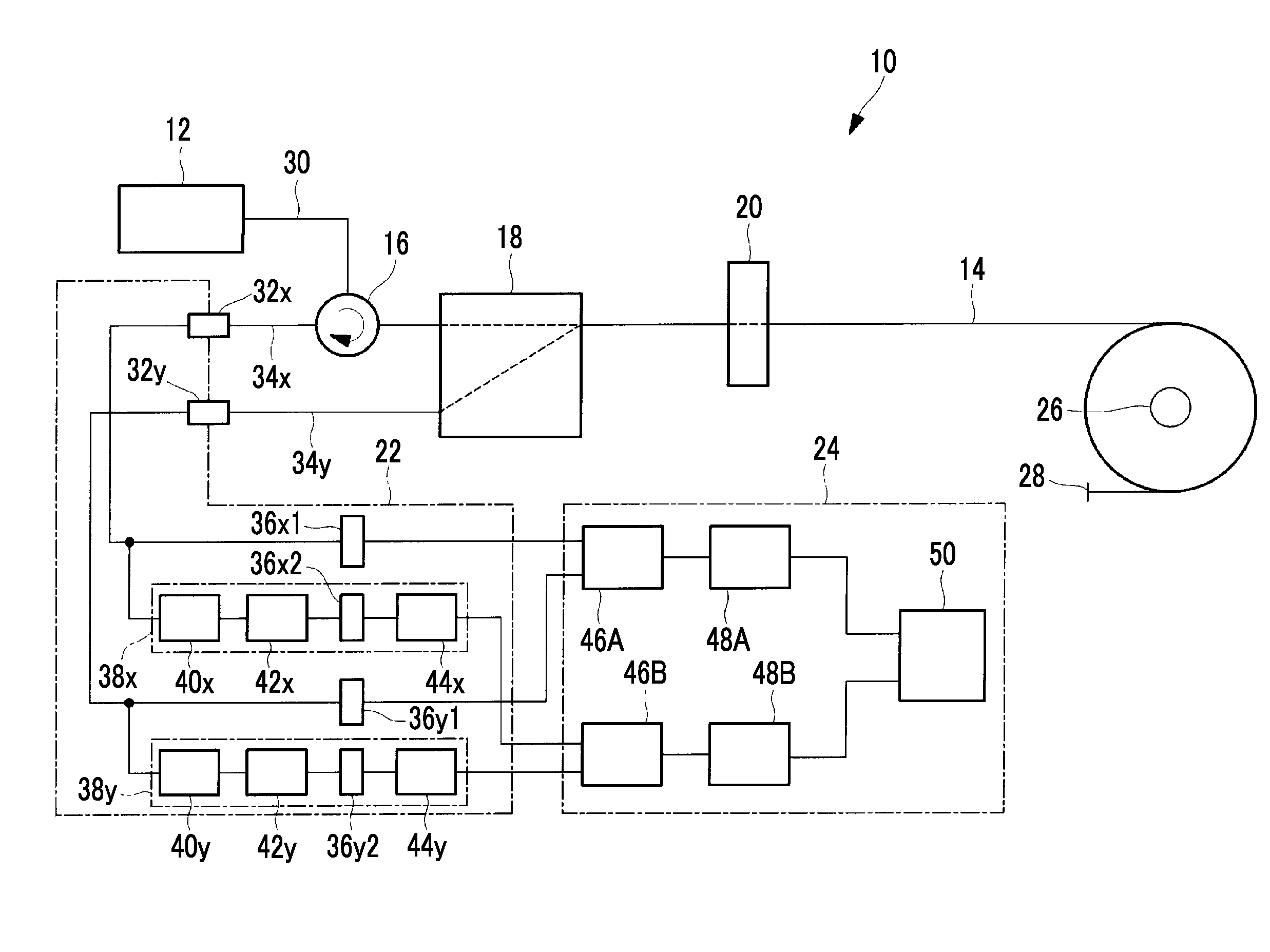
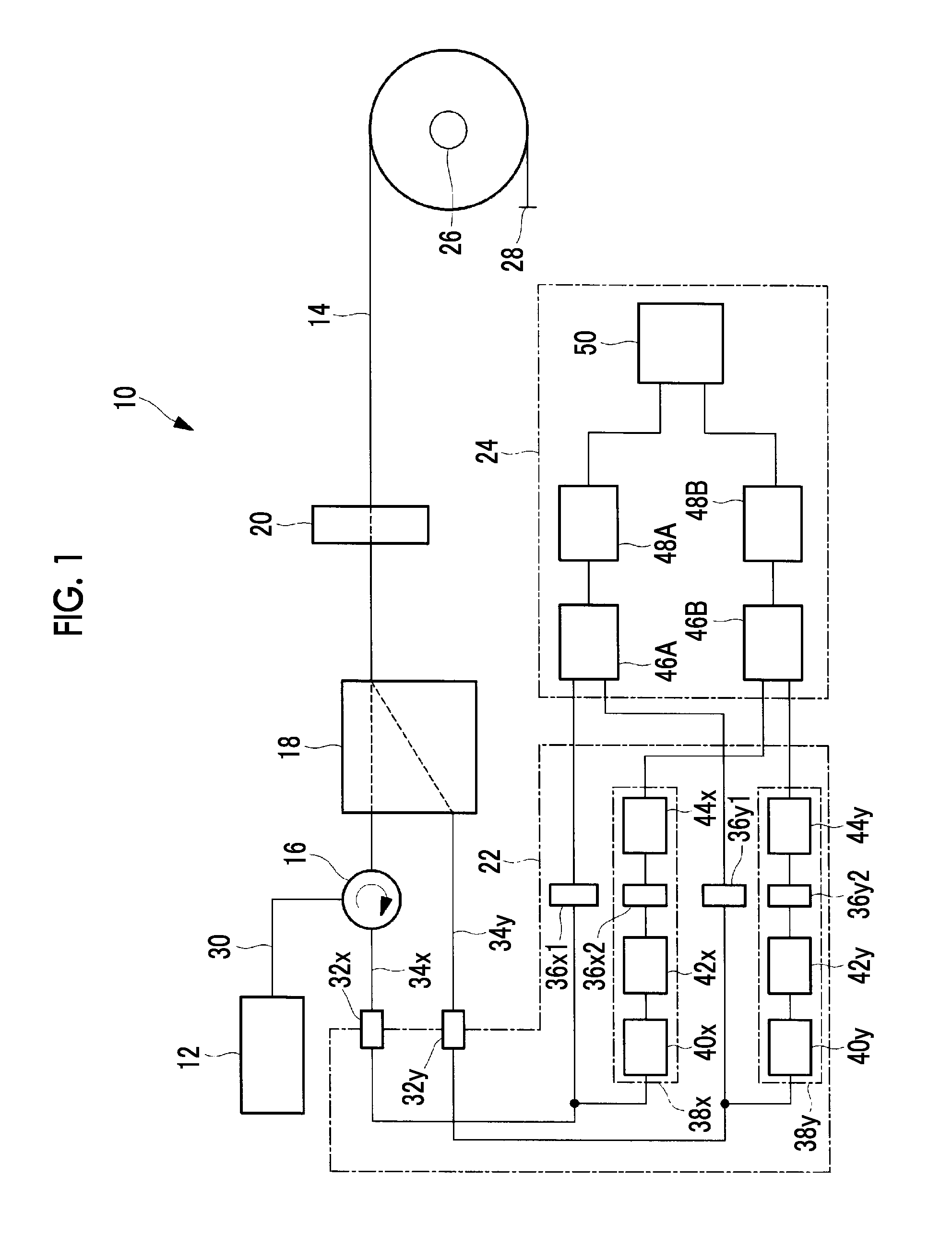
[0096]FIG. 6 shows a modification example of the lightning current measuring device 10.

[0097]As shown in FIG. 6, the lightning current measuring device 10 includes A / D converters 36x and 36y on the downstream side of the light receiving elements 32x and 32y. Accordingly, the configuration of the lightning current measuring device 10 is further simplified.

[0098]The lightning current measuring device 10 may perform the same processing as the offset removal performed in the small current processing units 38x and 38y for the signals Px and Py input to the Faraday rotation angle calculation unit 46A, that is, signals corresponding to the large current.

[0099]Although the invention has been described based on the above-described embodiment, the technical scope of the invention is not limited to the scope of description in the above-described embodiment. Various changes or improvements can be made to the above-described embodiment without departing from the spirit and scope of the invention...


PUM


Abstract

A lightning current measuring device is provided with: a polarized light separation element which separates light output from a sensor fiber into horizontal and vertical components having orthogonal planes of polarization, a Faraday rotation angle calculation unit calculating a Faraday rotation angle through arc-sine processing of a digitized signal of the difference between the horizontal and vertical components converted to a signal through photoelectric conversion after separation by the polarized light separation element, amplifiers which amplify the horizontal and vertical components converted to a signal through photoelectric conversion after separation by the polarized light separation element, a Faraday rotation angle calculating unit which calculates a Faraday rotation angle based on a digitized signal of the difference between the amplified horizontal and vertical components, and current value conversion units converting current values based on the calculated Faraday rotation angles.

Description

TECHNICAL FIELD[0001]The present invention relates to a lightning current measuring device and a lightning current measuring method.BACKGROUND ART[0002]Various kinds of crafts and buildings (for example, aircrafts, windmills, automobiles, and the like) may be struck by lightning. It is very important to measure a current (hereinafter, referred to as a “lightning current”) generated by a lightning strike or a current distribution in anti-lightning design.[0003]For example, as specified in SAE standard ARP5412.revA (see FIG. 7), the lightning current includes a large current (a region A of FIG. 7) which has a maximum peak equal to or greater than 100 kA (about 200 kA at the tip of the main wing of an aircraft and about 100 kA at the center of the main wing) and a pulse waveform from the rise to 500 μsec, a current (a region B of FIG. 7) which is 2 kA on average and gradually decreases to about 5 msec, and a small current (a region C of FIG. 7) which is 400 A on average and is maintain...

Claims


Application Information

Patent Timeline
Patent Type & Authority Applications(United States)
IPC IPC(8): G01R15/24G01R29/08
CPCG01R29/0842G01R15/246
Inventor AOI, TATSUFUMITSUMURA, YOICHIROKUROSAWA, KIYOSHIKIKUCHIHARA, YUTAKA
Owner MITSUBISHI HEAVY IND LTD
Why Eureka
Try Eureka