Device and method for stimulated raman detection

a technology of stimuli and raman, applied in the field of devices, can solve the problems of detection posing a different problem, low repetition rate (1 khz) is incompatible with fast-scanning microscopy, and is not suitable for biological imaging, etc., and achieves the effect of causing artifacts

Active Publication Date: 2016-02-18
UNIV DE PROVENCE D AIX MARSEILLE I +1
View PDF4 Cites 14 Cited by
  • Summary
  • Abstract
  • Description
  • Claims
  • Application Information

AI Technical Summary

Benefits of technology

[0016]electronic processing means making it possible to obtain, from electronic signals resulting from the synchronous detection, a signal characterizing the molecular vibrational resonance of the sample.
[0017]Thus, this novel device employs three exciting beams, at three preset wavelengths, the pairwise interactions of which in the sample at the first and second modulation frequencies allow both an SRL process and an SRG process to be generated at the same time, the beam of intermediate wavelength serving alternatively as pump beam or Stokes beam in each of the processes. The modulation frequencies may be identical or different depending on the embodiment. In both cases, synchronous detection at the modulation frequency or frequencies of the non-linear optical signals resulting from the interactions of the two processes allows artifacts to be suppressed and the useful SRS signal to be multiplied by two.
[0018]The means for making the pulse trains interact in the sample advantageously comprise means for focusing the pulse trains onto a common focusing volume, making it possible to obtain energy densities high enough to generate the non-linear optical effects in the sample.
[0019]The device described may be at least partially fibered. The Applicant has shown that the detection method implemented furthermore allows artifacts due to non-linear effects generated in the fiber to be suppressed.

Problems solved by technology

This type of system induces a strong SRS signal but is not however suitable for biological imaging.
Specifically, the high peak powers employed (of the order of a nJ) damage the samples, and the low repetition rates (1 kHz) are incompatible with fast-scanning microscopy.
In SRS microscopy, detection poses a different problem because the useful signal is generated at the same frequency as the exciting beams.
However, SRS microscopy is subject to a number of artifacts that limit chemical specificity because they introduce signals that can be interpreted as the SRS signal.
These artifacts are exacerbated by scattering media, especially biological tissues, and hinder the use of SRS microscopy to examine vibrational bonds having small effective Raman cross-sections.
Specifically, even when a collecting objective having a numerical aperture larger than that of the excitation objective is used, scattering will lead to diaphragming by the collecting objective which exacerbates the effect of the artifacts, especially the cross Kerr effect.

Method used


Image

  • Device and method for stimulated raman detection
  • Device and method for stimulated raman detection
  • Device and method for stimulated raman detection

Examples


Embodiment Construction

[0059]In the figures, identical elements are indicated by the same references.

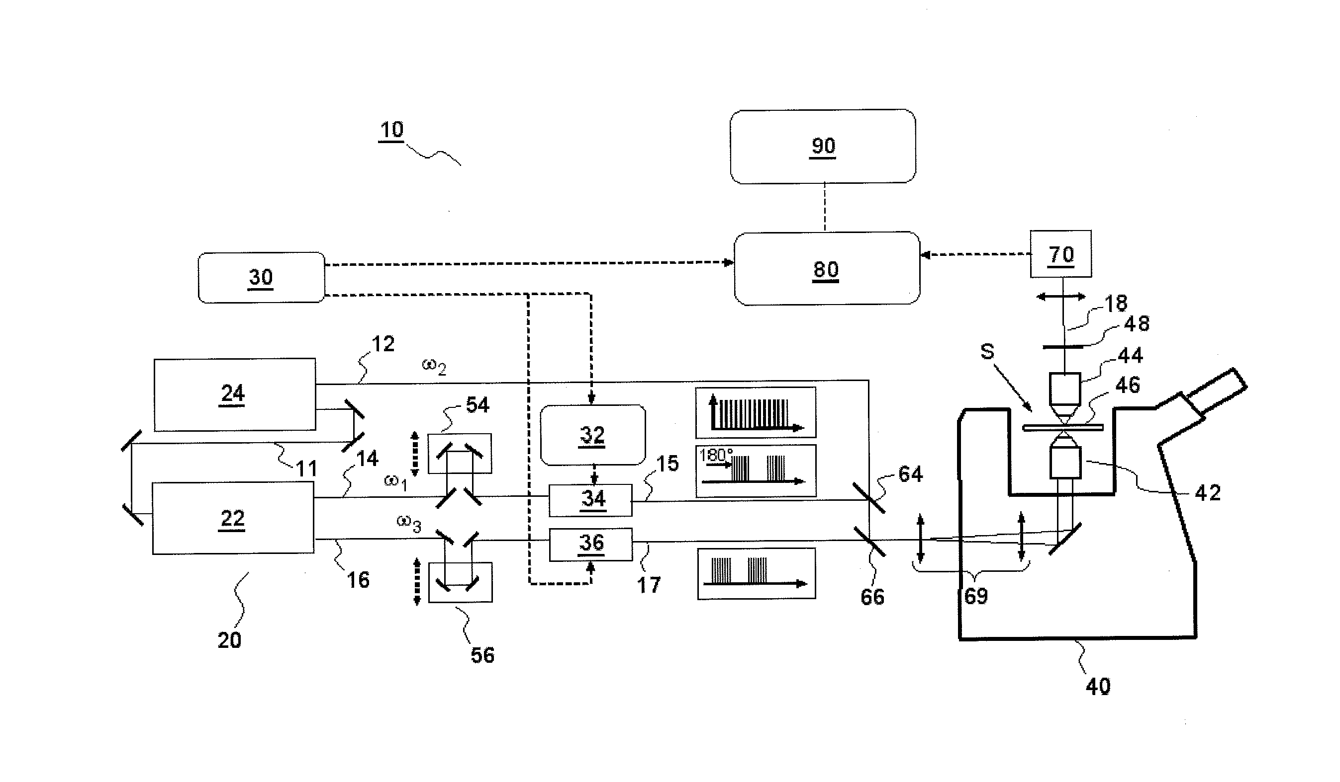
[0060]FIG. 4 shows an example of a device for detecting a non-linear resonant SRS optical signal according to one variant of the present invention, implementing amplitude modulation.

[0061]The detection device 10 comprises a source 20 for emitting trains of pulses centered on the angular frequencies ω1, ω2 and ω3, such that ω2−ω1=ω3−ω2=ΩR where ΩR is a molecular vibrational resonant frequency that it is sought to analyze in a sample S. The pulses are for example picosecond pulses, of a few cm−1 in spectral width, or may be frequency chirped pulses as will be described in more detail below. Typically, the trains of pulses for example comprise pulses of a few picoseconds, emitted at rates of a few tens of MHz, for example about 80 MHz, for a length of time of about one microsecond.

[0062]According to one variant, the emitting source 20 comprises a laser system consisting of a master laser 24 emitting trains 12...


PUM

PropertyMeasurementUnit
length of timeaaaaaaaaaa
wavelengthsaaaaaaaaaa

Abstract

According to one aspect, the invention relates to a device for detecting a resonant non-linear optical signal of Stimulated Raman Scattering (SRS) type induced in a sample. The device comprises electro-optical means for making interact in the sample, at a first modulation frequency, trains of light pulses of angular frequencies ω1 and ω2 and, at a second modulation frequency, trains of light pulses of angular frequencies ω2 and ω3, such that ω2−ω13−ω2R where ΩR is a molecular vibrational resonant angular frequency of the sample. Moreover, the device comprises means for synchronous detection at the first and second modulation frequencies of non-linear optical signals resulting from the interaction of the light pulses in the sample, and electronic processing means making it possible to obtain, from electronic signals resulting from the synchronous detection, a signal characterizing the molecular vibrational resonance of the sample.

Description

TECHNICAL FIELD OF THE INVENTION[0001]The present invention relates to a device and a method for detection of a resonant non-linear optical signal of Stimulated Raman Scattering (SRS) type in a sample. It is especially applicable to microscopy imaging, to spectroscopy and to hyperspectral imaging in scattering media such as biological media.PRIOR ART [0002]Every chemical bond possesses vibrational frequencies that are specific to it. Methods that aim to use interaction between light and matter to obtain information on these molecular vibrations are called vibrational optical techniques. The best-known of these techniques is infrared (IR) spectroscopy, in which specific absorption lines of chemical bonds present in a sample are observed. Discovered in 1928, Raman scattering (named after the physicist Chandrasekhara Venkata Raman who discovered the effect) allows visible light to be used to obtain the vibrational spectrum of molecules that interact with light beams. In a Raman scatter...

Claims


Application Information

Patent Timeline
Patent Type & Authority Applications(United States)
IPC IPC(8): G01N21/65
CPCG01N2201/06113G01N21/65G01N2021/655
Inventor BERTO, PASCALANDRESEN, ESBENRIGNEAULT, HERVE
Owner UNIV DE PROVENCE D AIX MARSEILLE I
Why Eureka
Try Eureka