Expandable sheath assembly and method of using same

a sheath and expansion technology, applied in the field of expandable sheath assemblies, can solve the problems of increasing the risk of dissection, so as to reduce the risk of re-access complications, reduce the risk of hoop stress/dilation, and reduce the risk of sheath damage to the patien

Active Publication Date: 2016-03-10
FREUDENBERG MEDICAL
View PDF8 Cites 8 Cited by
  • Summary
  • Abstract
  • Description
  • Claims
  • Application Information

AI Technical Summary

Benefits of technology

[0012]The subject expandable sheath assembly and method of using same advantageously allows the proximal sheath, which has a larger diameter than a lower profile diameter of the dilator, to be slidably advanced into the body vessel. The lifting of the distal sheath to expand the sheath assembly, and thus the body vessel, also avoids the need to push the proximal sheath past any calcification that is present within the body vessel, and further provides tactile feedback to a user while inserting the...

Problems solved by technology

However, the use of introducer sheaths and/or medical devices which are large relative to the body vessels to which they are inserted poses risks and challenges to both the patient and the physician.
For example, relative to femoral sheaths and catheters, larger introducer sheaths create sizeable arteriotomies in the femoral artery which cause more trauma to the patient, such as through artery avulsion, and create more challenges in placement of the sheath with risk of dissection.
In addition, the forces required by the physician to insert the larger introducer sheaths and/or medical devices into the body vessel can be higher than desired and create medical issues for the patient if calcification within the body vessel is dislodged during insertion of the introducer sheath and/or medical device.
However, such r...

Method used


Image

  • Expandable sheath assembly and method of using same
  • Expandable sheath assembly and method of using same
  • Expandable sheath assembly and method of using same

Examples


Embodiment Construction

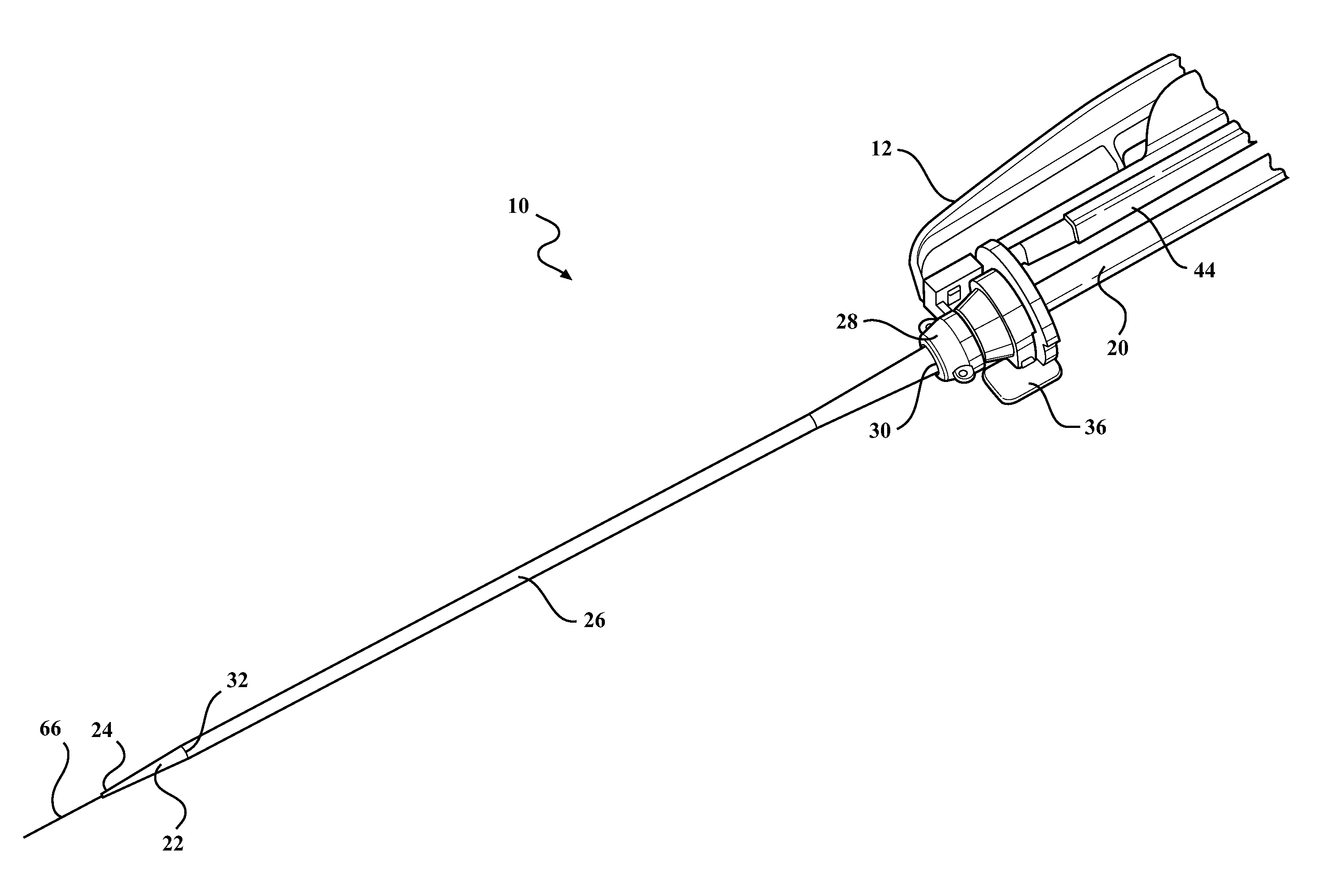
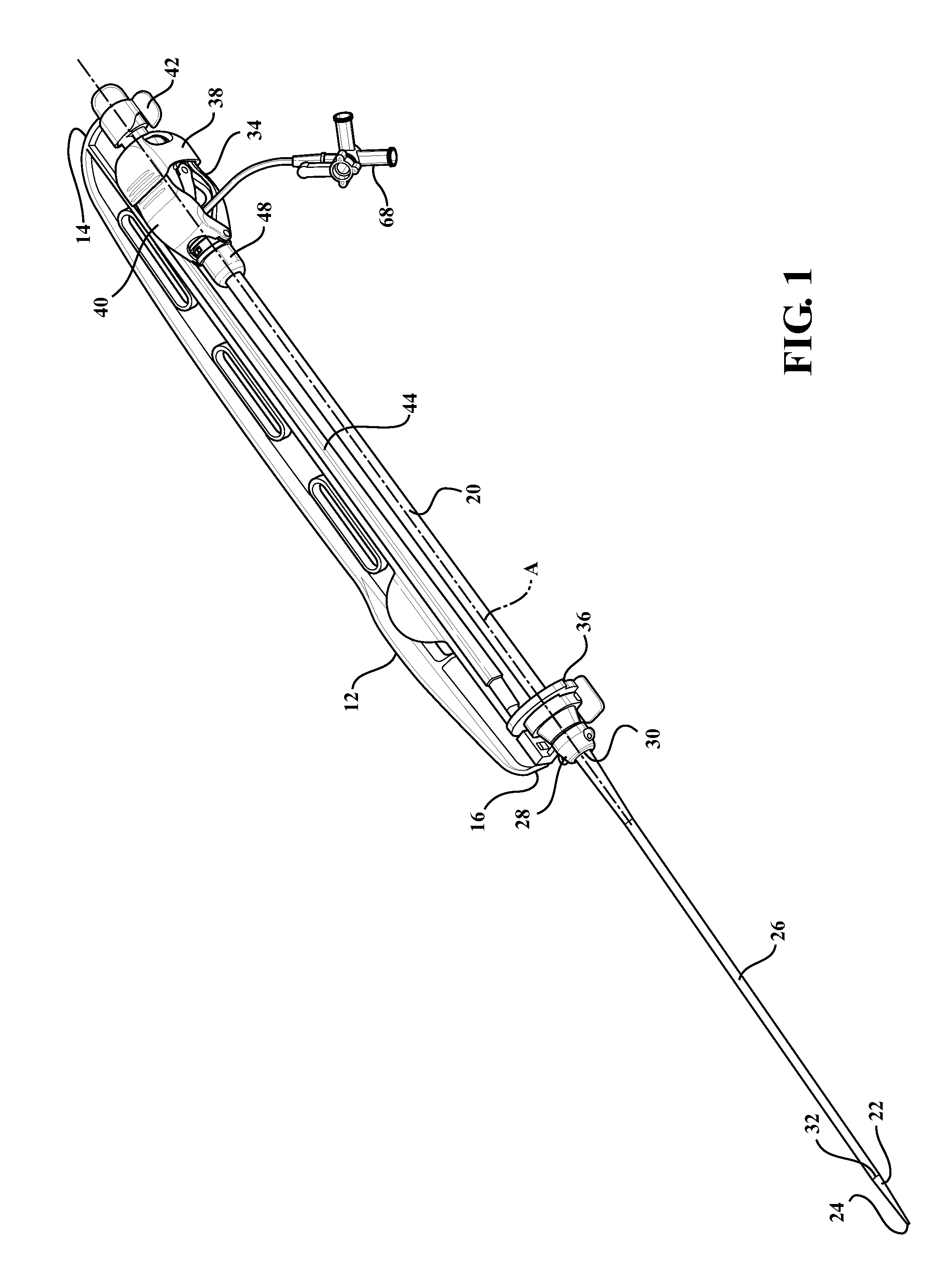
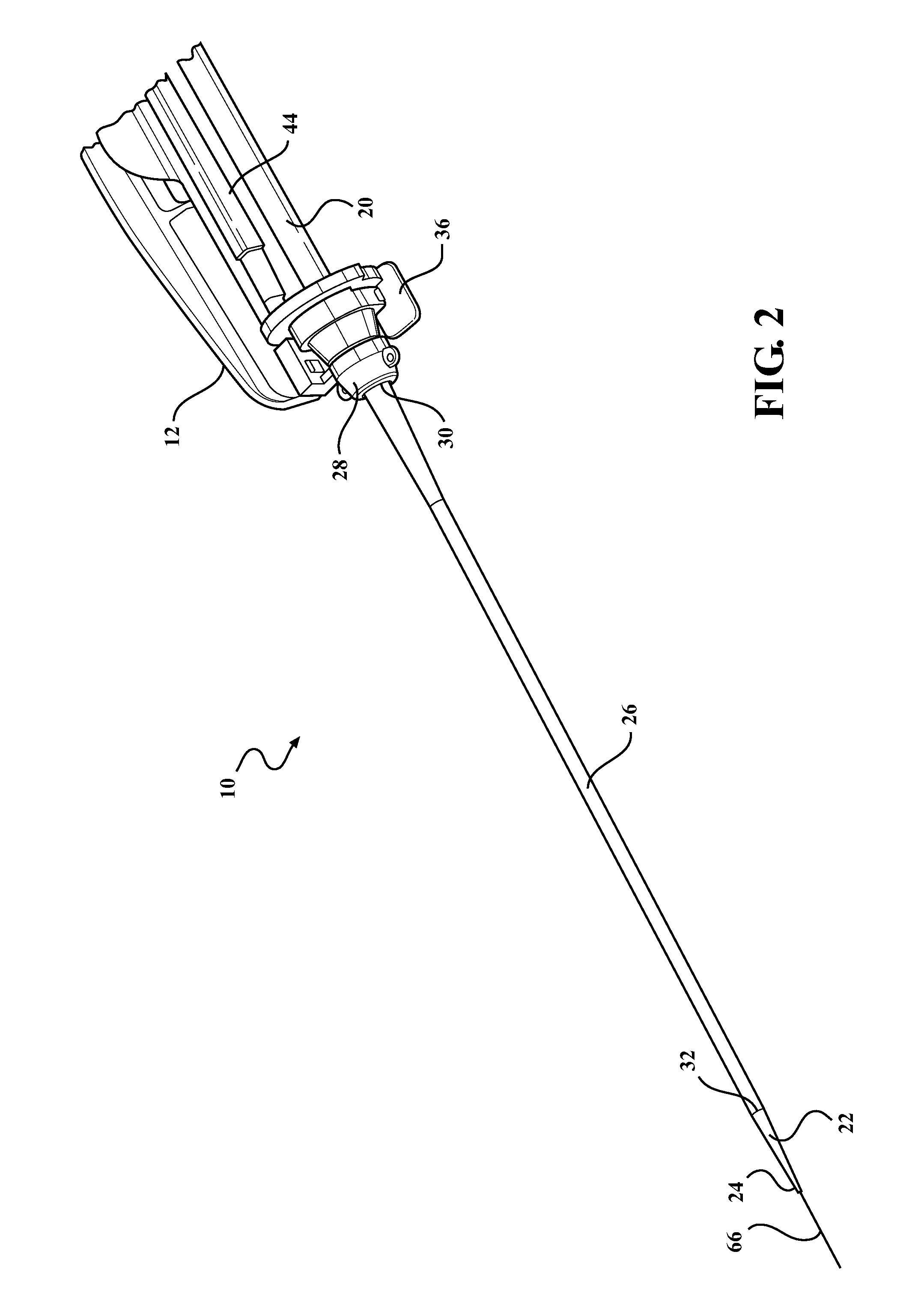
[0024]Example embodiments will now be described more fully with reference to the accompanying drawings. The example embodiments are provided so that this disclosure will be thorough and fully convey the scope to those skilled in the art. Numerous specific details are set forth such as examples of specific components, devices, mechanisms, assemblies, and methods to provide a thorough understanding of various embodiments of the present disclosure. It will be apparent to those skilled in the art that specific details need not be employed, that example embodiments may be embodied in many different forms, and that neither should be construed to limit the scope of the disclosure. With this in mind, the present disclosure is generally directed to expandable sheath assemblies of the type used to introduce and withdrawal a medical device (i.e., catheter systems, implants, etc.) into a body vessel of a patient.

[0025]Referring to the Figures, wherein like numerals indicate corresponding parts ...


PUM


Abstract

An expandable sheath assembly includes a support body extending from a proximal end to a distal end. A guide rod is interconnected to the support body and extends between the ends along an axis. A dilator extends from the guide rod for insertion into a body vessel, and a hub is releasable connected to the distal end of the support body. A distal sheath overlays the dilator, and a hemostatic valve is slidably disposed along the axis. A proximal sheath extends from the hemostatic valve and is disposed in surrounding and coaxial relationship with the guide rod. The proximal sheath is concurrently slidable with the hemostatic valve along axis to advance the proximal sheath through the hub and interleave the proximal sheath between the dilator and the distal sheath for lifting the distal sheath from the dilator and effectuating an expansion of the body vessel.

Description

BACKGROUND OF THE INVENTION[0001]1. Field of the Invention[0002]The present disclosure relates generally to medical devices and procedures. In particular, the present disclosure relates to expandable sheath assemblies, and methods of using the same.[0003]2. Description of the Prior Art[0004]This section provides background information related to the present disclosure which is not necessarily prior art.[0005]Numerous procedures have been developed that involve the percutaneous insertion of a medical device into the body of a patient, with the medical device being introduced into the body by a variety of known techniques. For example, access to coronary arteries, carotid arteries, the aorta, and peripheral vessels or other tubular members of the body for percutaneous therapeutic, diagnostic, and guide catheters is often made through introducer sheaths which are positioned into body vessels from outside the bodies. Such access sites include, but are not limited to, the common femoral ...

Claims


Application Information

Patent Timeline
IPC IPC(8): A61M25/06A61B17/34A61M25/09A61M29/00A61M39/06
CPCA61M25/0662A61M29/00A61M25/09A61B17/3415A61B17/3417A61M2039/062A61B17/3498A61M39/06A61M2025/0681A61M2025/0687A61B17/3468A61M2025/0004A61M2025/0024A61M2039/0673
Inventor FURNISH, GREGAPPLING, ANTHONYFURNISH, SIMONGUNASEKARA, ASELA INDAKAMORRIS, BEN
Owner FREUDENBERG MEDICAL
Why Eureka
Try Eureka