Head-wearing wireless control transcranial electrical stimulation device

a wireless control and transcranial electrical stimulation technology, applied in the field of cranial nerve bioelectrical stimulation devices, can solve the problems of increased operation cost, lower overall efficiency, and longer operation time, and achieve the effect of convenient portability and operation

Inactive Publication Date: 2016-03-17
ADVANCE ELECTRONICS & MEDICAL IND COMPANY
View PDF1 Cites 35 Cited by
  • Summary
  • Abstract
  • Description
  • Claims
  • Application Information

AI Technical Summary

Benefits of technology

[0021]The present invention is easy to carry and operate, integrates the AC and DC stimulation discharging modes, and has a multi-mode adjustable stimulation current and stimulation frequency. The

Problems solved by technology

Firstly, the TES technology comprises two discharging stimulation methods, respectively the transcranial direct current stimulation (TDCS) and the transcranial alternating current stimulation (TACS). Significant differences exist between the electricity generation mechanisms of the two discharging stimulation methods. Thus, during the practical application, the operator requires to use different single devices or accessories to finish the corresponding TES task, leading to the increased operation cost, the longer operation time, and the lower overall efficiency.
Secondly, the conventional TES devices available on the market have a table-shaped design, a large volume, a clumsy appearance and inconvenience in carrying. During operation, the conventional TES devices mainly adopt the alternating current (110-220V AC) to serve as the power supply, potentially risky. Moreover, the users are unable to use the conventional TES devices outdoors, because of the lack of the flexibility and the mobility.
Thirdly, in all of the conventional TES devices, the electrode plates are connected with the shielded wires. The electrode plates contact the scalp, through the conductive adhesives or the thin sponges soaked with the saline as the medium. According to the encephalic region to be stimulated, the operator finds corresponding positions on the head of the person to be stimulated, and then respectively fixes the different electrode plates on the head through the elastic adhesive tapes. Thus, during the whole TES process, be

Method used


Image

  • Head-wearing wireless control transcranial electrical stimulation device
  • Head-wearing wireless control transcranial electrical stimulation device
  • Head-wearing wireless control transcranial electrical stimulation device

Examples


Embodiment Construction

[0028]The present invention is further illustrated with accompanying drawings and a preferred embodiment, in such a manner that one skilled in the art will better understand and implement the present invention. However, the embodiment of the present invention as shown in the drawings and described below is exemplary only and not intended to be limiting.

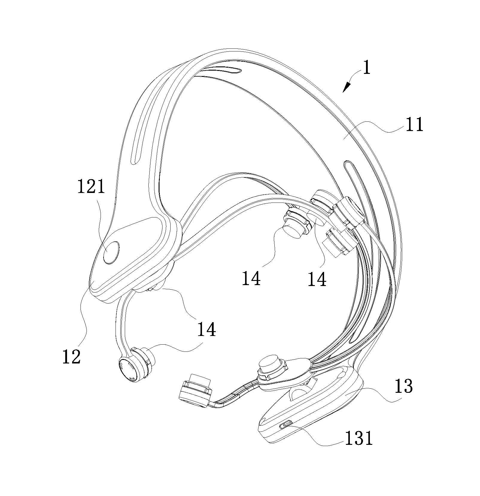
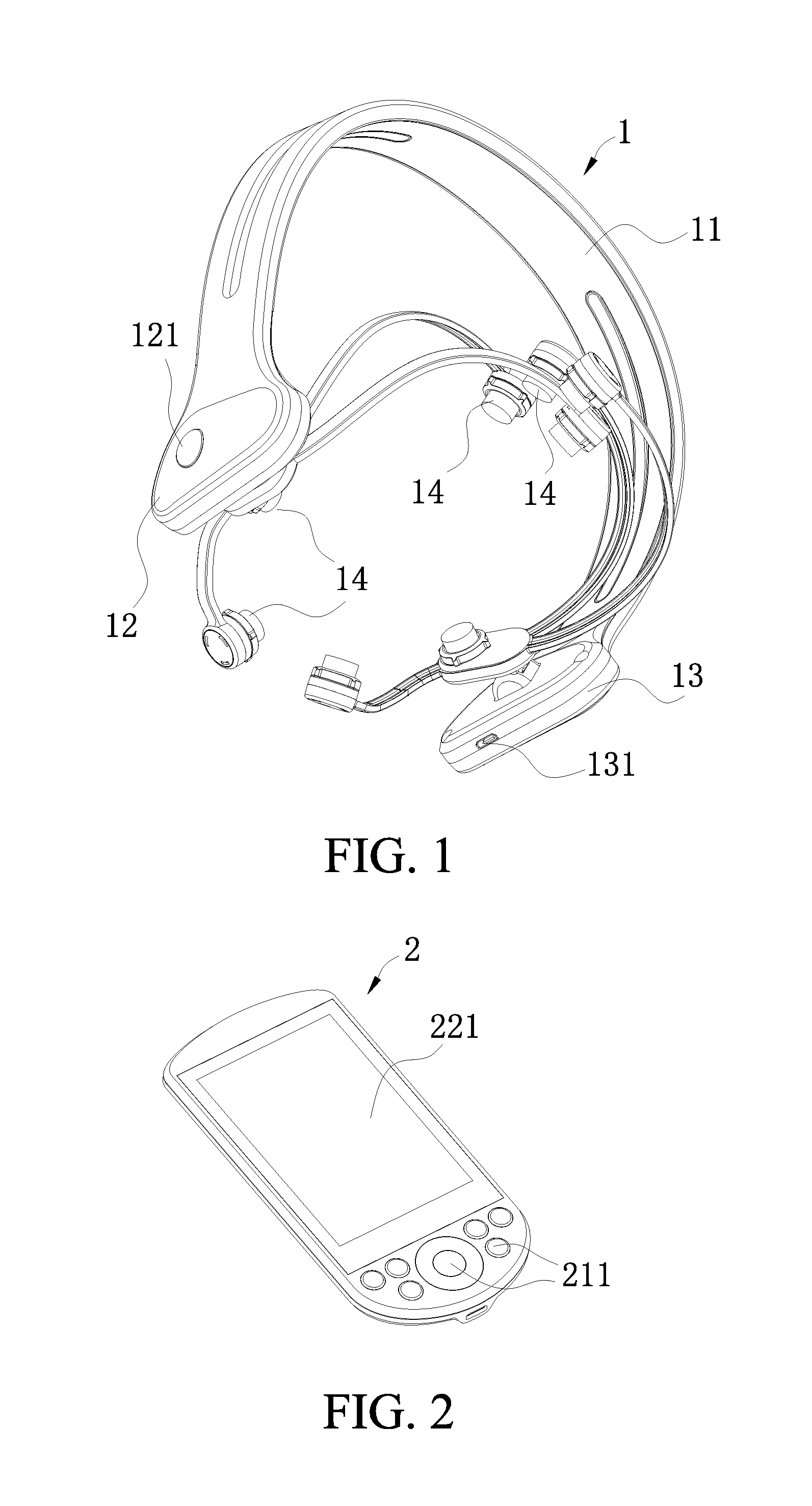
[0029]Referring to FIGS. 1-4, according to a preferred embodiment of the present invention, a head-wearing wireless control transcranial electrical stimulation device comprises a head-wearing part 1 and a remote control part 2, wherein:

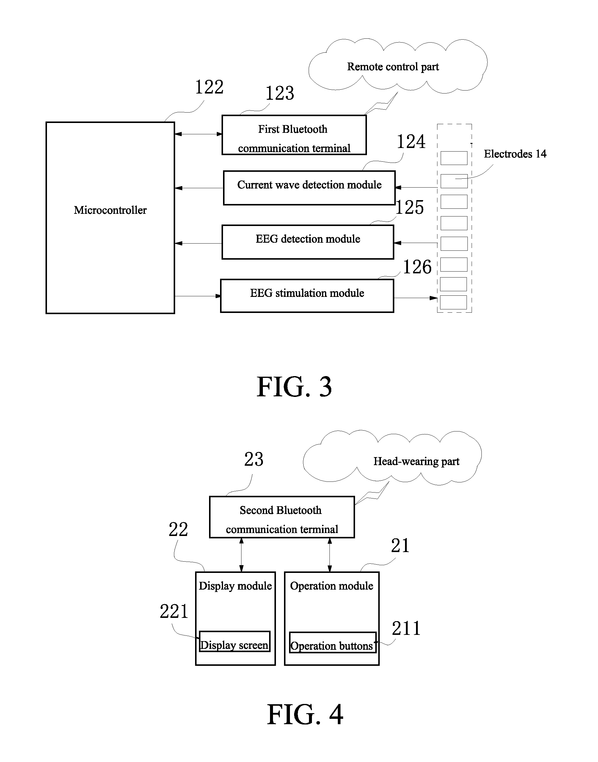
[0030]the head-wearing part 1 comprises an arch-shaped elastic clamper 11; an integrated circuit board (not showed in the figures) which is started by a switch 121 is arranged within a cavity 12 of a first end of the elastic damper 11; a microcontroller 122 which is connected with a first Bluetooth communication terminal 123 is arranged on the integrated circuit board; a power supply 131 is arranged wit...


PUM


Abstract

A head-wearing wireless control transcranial electrical stimulation device includes a head-wearing part and a remote control part. An integrated circuit board is arranged within a cavity of a first end of the head-wearing part. The integrated circuit board controls a microcontroller. The microcontroller is connected with and controls a plurality of electrodes for contacting a human body through circuit modules. The microcontroller receives a control instruction from the remote control part through a Bluetooth communication terminal, and then controls the plurality of the electrodes to exert an alternating current or a direct current having preset density and frequency to a cerebral cortex. The microcontroller receives an electrode feedback signal, and sends the electrode feedback signal after being pre-processed to a display module of the remote control part to be displayed through the Bluetooth communication terminal.

Description

CROSS REFERENCE OF RELATED APPLICATION[0001]The present application claims priority under 35 U.S.C. 119(a-d) to CN 201420830404.9, filed Dec. 23, 2014.BACKGROUND OF THE PRESENT INVENTIONField of Invention[0002]The present invention relates to a field of a cranial nerve bioelectrical stimulation device, and more particularly to a head-wearing wireless control transcranial electrical stimulation device.Description of Related Arts[0003]Transcranial electrical stimulation (TES) technology is a noninvasive technology which adjusts activities of nerve cells of the cerebral cortex through a weak current (0.5-2.0 mA). Since the 1990s, people have widely researched on the TES. With the continuous deepening of the research on the central nervous system and the neuroscience, people have a deeper understanding towards the TES, and meanwhile the application of the TES in treating the nerve diseases and the mental diseases, learning the motor skill and increasing the brain cognitive ability becom...

Claims


Application Information

Patent Timeline
IPC IPC(8): A61N1/04A61N1/36A61N1/20A61N1/372
CPCA61N1/36014A61N1/37217A61N1/20A61N1/0476A61N1/0526A61N1/36025A61N1/0456A61N1/36031A61N1/18A61N1/32
Inventor KWAN, PUI TONGKONG, XIANG HUIZHAO, YU
Owner ADVANCE ELECTRONICS & MEDICAL IND COMPANY
Why Eureka
Try Eureka