Method for manufacturing a tipped circular saw blade

a technology of circular saw blades and manufacturing methods, which is applied in the direction of metal sawing tools, metal sawing tools, metal-working equipment, etc., can solve the problems of inability to change the order of steps or simultaneous execution of some of these steps, production costs are high, and production time cannot be drastically reduced, so as to achieve high positioning accuracy and high positioning accuracy. , the effect of high accuracy

Inactive Publication Date: 2016-03-24
KANEFUSA HAMONO KOUGIYOU KK
View PDF16 Cites 8 Cited by
  • Summary
  • Abstract
  • Description
  • Claims
  • Application Information

AI Technical Summary

Benefits of technology

[0013]In addition, in the present invention, preferably, part of both side faces of each one of the cutting edge tips are provided with parts parallel to each other, or parts slanted to depart from each other as they go in an opposite direction to a cutting edge of the cutting edge tip. When part of both non-parallel side faces of each one of the cutting edge tips having a radial clearance angle and a tangential clearance angle are provided with faces parallel to each other and the cutting edge tip is pressed against and welded to the tooth, the cutting edge tip can be stably clamped by the parallel faces and therefore can be pressed against the tooth with a high positioning accuracy. On the other hand, when part of both the non-parallel side faces are provided with parts slanted to depart from each other as they go in an opposite direction to a cutting edge of the cutting edge tip, the cutting edge tip clamped by the slanted parts is strongly pressed toward the tooth and therefore can be pressed against the tooth with a high positioning accuracy. As a result, in the present invention, the cutting edge tip can be welded to the tooth with high accuracy, and a circular saw blade having minimum height differences of the plurality of tips, that is to say, the circular saw blade with a high cutting performance can be produced with ease. It should be noted that even if the tips are not coated by omitting the third step, similar effects to the abovementioned ones can be obtained in the present invention.
[0014]Furthermore, in the present invention, the base metal can have a thickness of 3.7×(1/105)×D2 [mm] or less, where D is a diameter [mm] of the base metal. Since the metal base in itself is not held at a coating treatment temperature of about several h...

Problems solved by technology

This is why production is carried out in the above sequence of steps, and change in the order of steps or simultaneous execution of some of these steps is impossible.
As a result, in the above manufacturing method, a sum of production time of each of the four steps is necessary and production costs are high.
Besides, production time cannot be drastically reduced.
In such a case, it is necessary to prepare a PVD device large enough for the diameter of the circular saw blade, but such a PVD device is very expensive.
Therefore, depending on the volume of production, financial burden of device costs is very high.
Furthermore, in a case of such a large-diameter circular saw blade, great efforts are necessary to apply coating pretreatment and to place the circular saw blade in devices for coating, so production costs increase even more.
Because, in coating, a disk-shaped base plate is greatly deformed or buckled by a relatively small thermal stress, it is difficult to form a coating film which is good both in film quality an...

Method used


Image

  • Method for manufacturing a tipped circular saw blade
  • Method for manufacturing a tipped circular saw blade
  • Method for manufacturing a tipped circular saw blade

Examples


Embodiment Construction

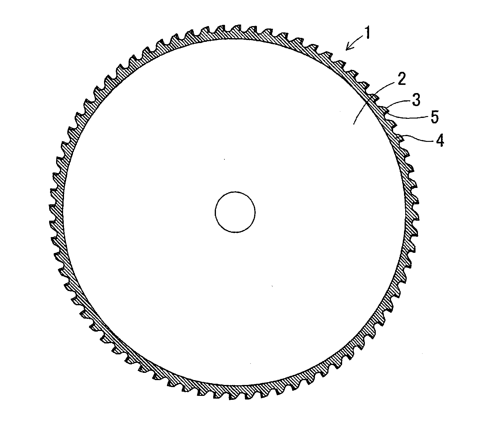
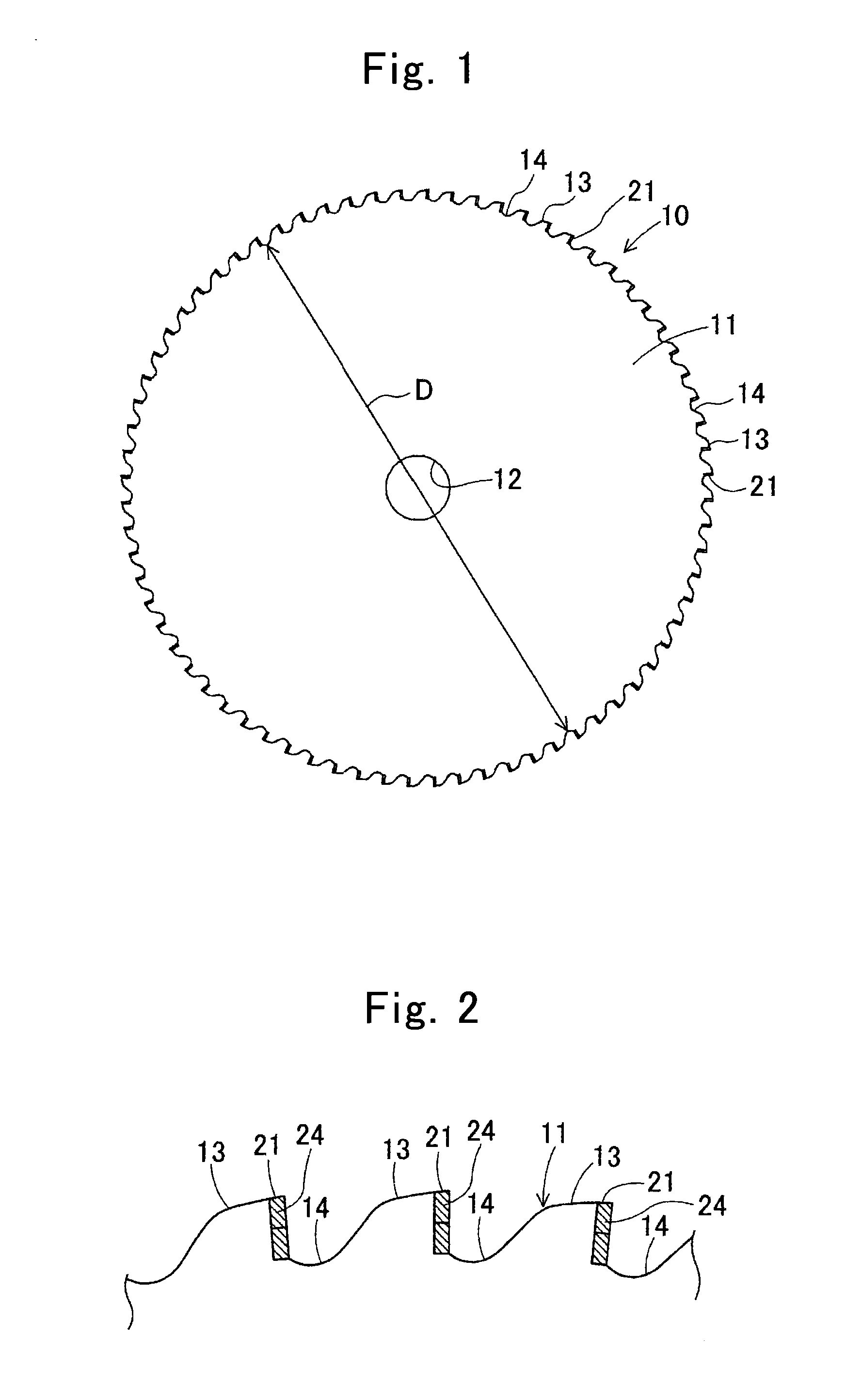
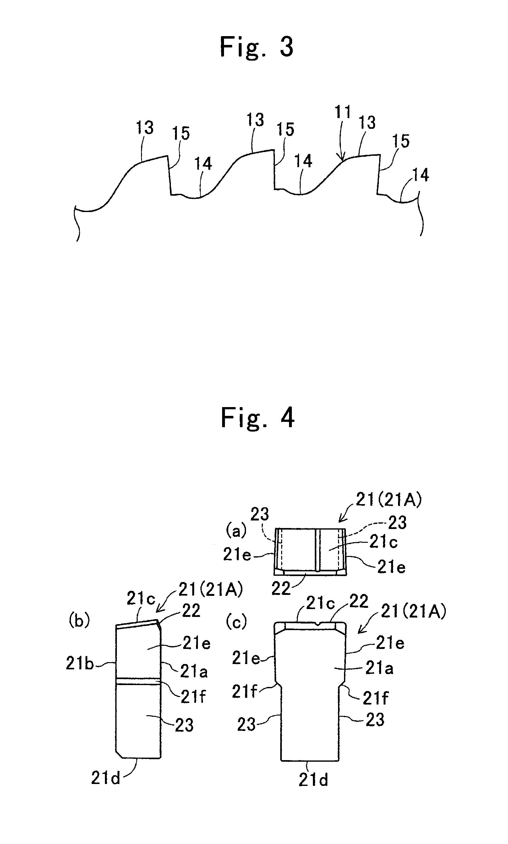
[0027]Hereinafter, embodiments of the present invention will be described with reference to drawings. FIG. 1 is a front view of a tipped circular saw blade (hereinafter referred to as a circular saw blade) 10 according to an example. FIGS. 2 and 3 are partially enlarged front views of the circular saw blade 10 and a metal base 11. The metal base 11 constituting the circular saw blade 10 is a thin disk-shaped plate of steel, and has a central hole 12 into which a rotary shaft of machining equipment is inserted. At an outer periphery of the metal base 11, a number of roughly quadrangular teeth 13 protrude radially at circumferentially even intervals, and gullets 14 relatively recede radially between the teeth 13. On a leading edge side of the teeth 13 in a forward direction of rotation, a number of mounting seats 15 are formed by being cut out at a roughly right angle for mounting cutting edge tips 21.

[0028]The cutting edge tips 21 are welded on the mounting seats 15 by brazing or the...


PUM


Abstract

A method for manufacturing a tipped circular saw blade includes forming a disk-shaped metal base producing cutting edge tips by grinding cutting edges, coating the cutting edge tips with hard coating film, fixing the cutting edge tips coated with the hard coating film to teeth of the metal base by brazing. The hard coating film is of one material selected from a first material including one of nitrides, oxides or oxynitrides containing at least one of Al, Ti, and Cr, a second material including the first material containing at least one of Si, V, Ni, Y, Zr, Nb, Mo, Ta and W, a third material including the first material including at least one of B and C, and a fourth material including the second material containing at least one of B and C.

Description

TECHNICAL FIELD[0001]The present invention relates to a method for manufacturing a tipped circular saw blade which is formed by fixing cutting edge tips to a disk-shaped metal base by welding and used for cutting a variety of materials such as metal, wood, plastic, and ceramics or other purposes, and particularly to a method for manufacturing a tipped circular saw blade whose cutting edges coated with hard coating film.BACKGROUND ART[0002]As an example of a conventional method for manufacturing such a tipped circular saw blade, Japanese Unexamined Patent Application Publication No. H11-239,915 discloses a method for manufacturing a disk-shaped tool comprising brazing tips formed of cemented carbide, cermet, an abrasion-resistant casting alloy or the like to a disk-shaped base plate (a metal base) of steel and then coating the tips by a physical vapor deposition process (hereinafter referred to as a PVD process). In this manufacturing method, steps of producing a disk-shaped base pla...

Claims


Application Information

Patent Timeline
IPC IPC(8): B23D65/00B23D61/02B23D61/04
CPCB23D65/00B23D61/04B23D61/028
Inventor FUJIWARA, TSUGUNORIIINUMA, TOMOYUKI
Owner KANEFUSA HAMONO KOUGIYOU KK
Why Eureka
Try Eureka