Process for producing reaction bonded silicon carbide member

a technology of reaction bonding and silicon carbide, which is applied in the direction of additive manufacturing processes, electric/magnetic/electromagnetic heating, manufacturing tools, etc., can solve the problems of low silicon carbide filling rate, poor handling of silicon carbide green body, and low silicon carbide in the green body. , to achieve the effect of satisfactory amount of silicon, excellent ceramic properties, and high porosity

Inactive Publication Date: 2016-03-24
TOTO LTD
View PDF10 Cites 16 Cited by
  • Summary
  • Abstract
  • Description
  • Claims
  • Application Information

AI Technical Summary

Benefits of technology

[0007]The present inventors have now found that merely subjecting to impregnation a green body of silicon carbide obtained by a SLS process with carbon and an infiltration with silicon and then reaction sintering cannot realize a RBSiC member which has excellent ceramic properties unless the amount of carbon impregnated is taken into consideration. Further, when the amount of carbon impregnated with a gree

Problems solved by technology

This leads to a low proportion (filling rate) of silicon carbide in the green body and a low density.
As a result, the strength of the green body is low.
Conse

Method used


Image

  • Process for producing reaction bonded silicon carbide member
  • Process for producing reaction bonded silicon carbide member
  • Process for producing reaction bonded silicon carbide member

Examples


example 1

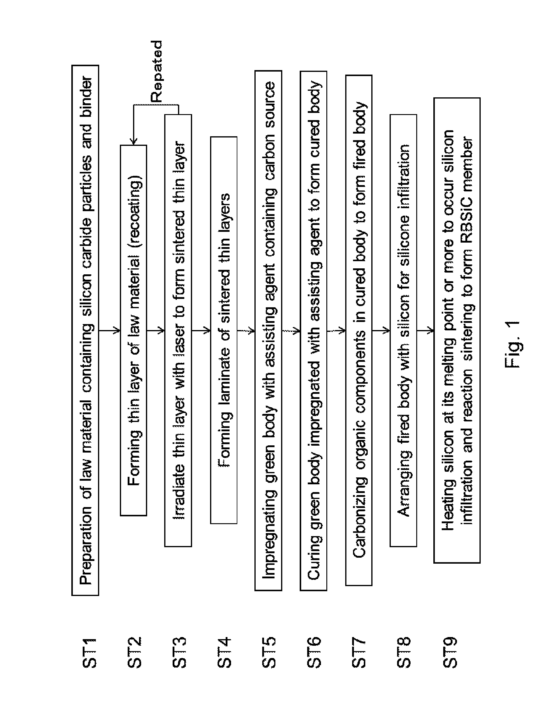
Preparation of Raw Material

[0108]Silicon carbide (SiC) having a mean particle diameter of 30 μm and nylon 12 having a mean particle diameter of 10 μm were provided for use in a raw material. The silicon carbide powder and nylon 12 were weighed so that the weight ratio (silicon carbide powder:nylon 12) was 100:1. The mixed powder (10 kg) was introduced into a plastic pot, followed by dry stirring mixing for 2 hr or longer to give a raw material.

[0109]Preparation of Green Body

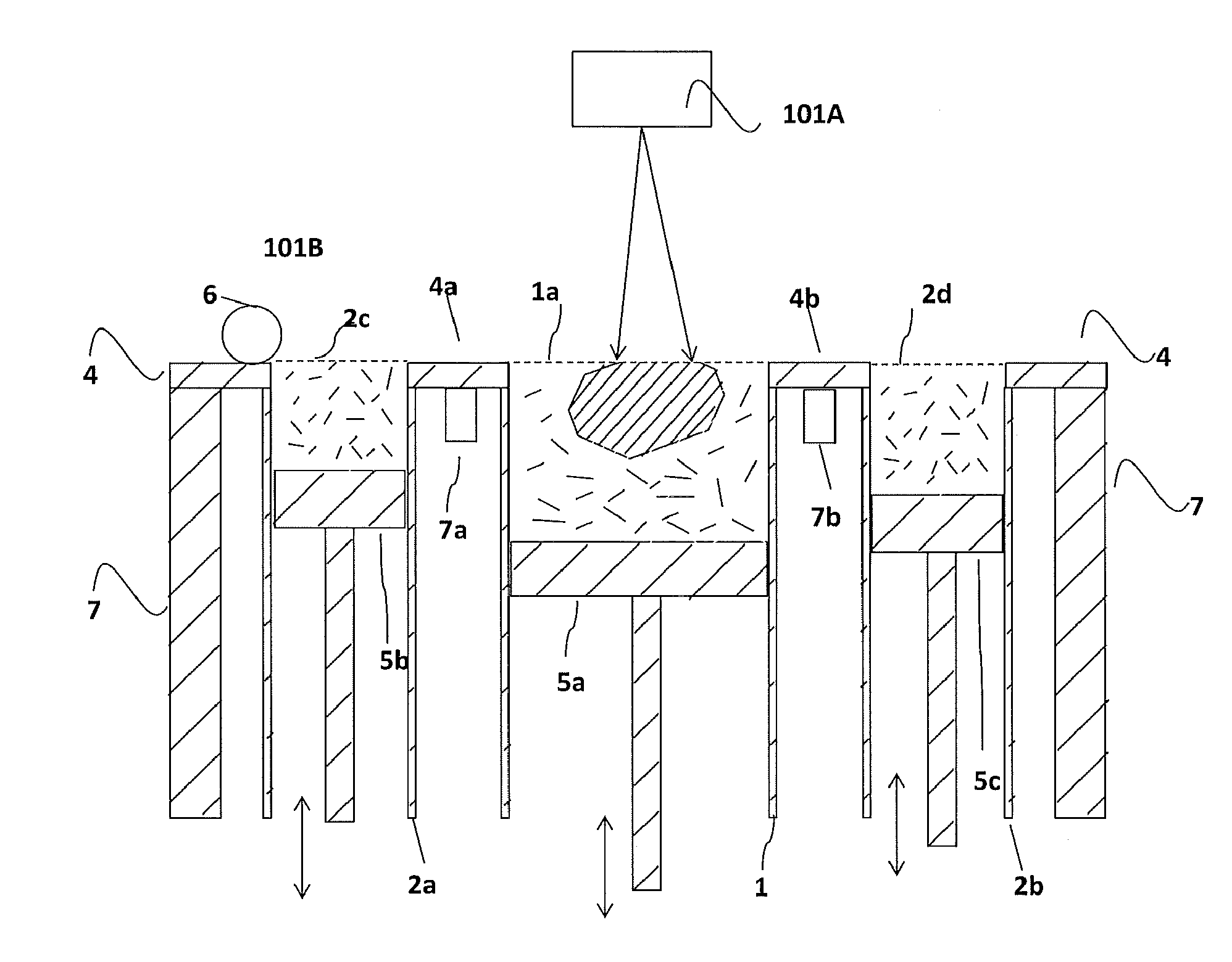
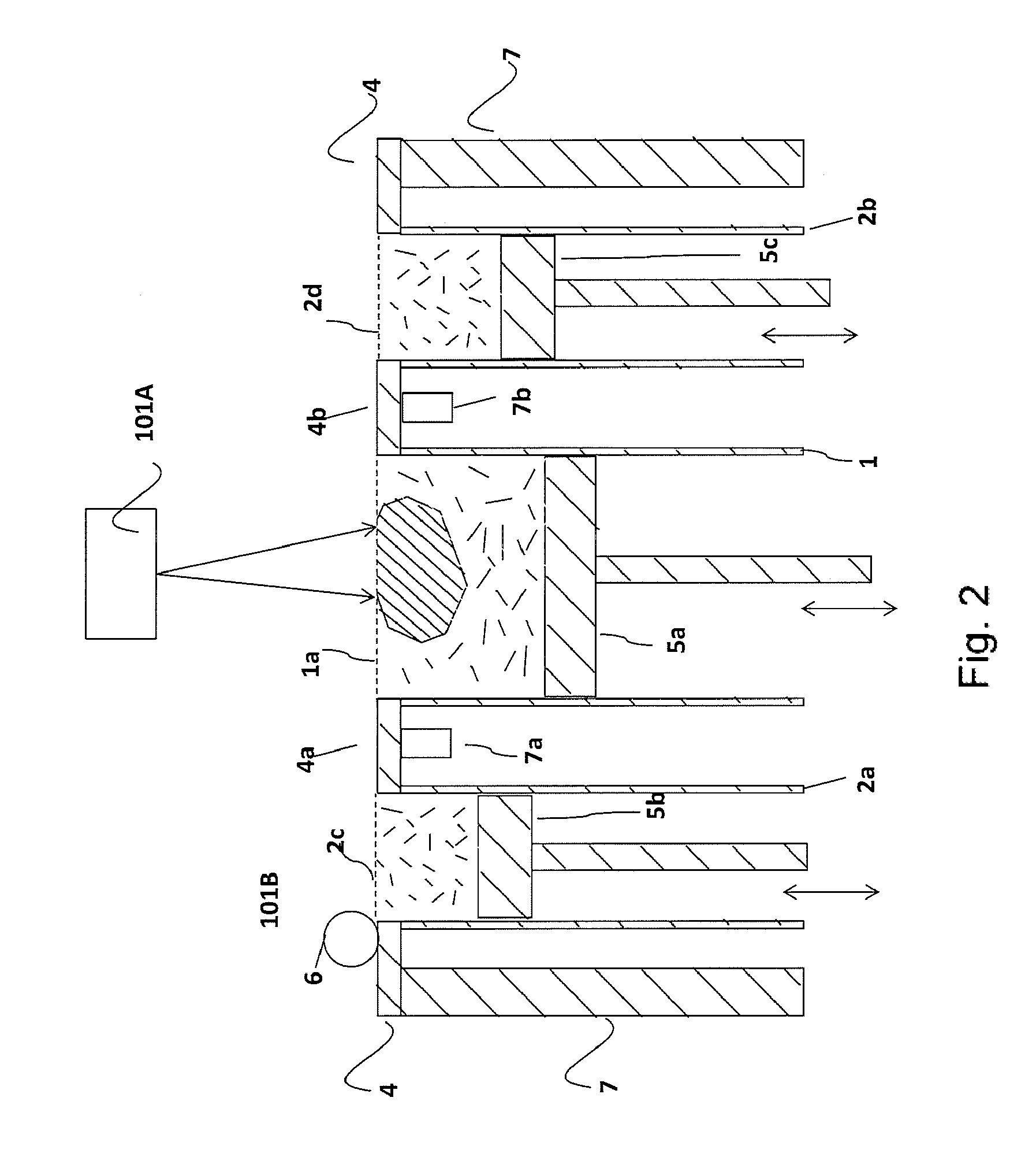
[0110]A powder lamination-type 3D forming apparatus (SEMplice300, manufactured by Aspect) was used as a SLS apparatus. A predetermined amount of the raw material thus obtained was introduced and evenly filled into a raw material vessel. Subsequently, the raw material vessel filled with the raw material was set in an apparatus body, and nitrogen was introduced into a forming chamber. Further, a thin layer of the raw material was previously formed in a predetermined thickness on a forming table within a forming cha...

example 2

[0124]A RBSiC member was prepared in the same manner as in Example 1, except that the raw material was obtained at a weight ratio of silicon carbide powder to nylon 12 of 100:3. Further, in the same manner as in Example 1, silicon on the surface of the RBSiC member was removed to give a desired shape, followed by various evaluations.

example 3

[0125]A RBSiC member was prepared in the same manner as in Example 1, except that the raw material was obtained at a weight ratio of silicon carbide powder to nylon 12 of 100:10. Further, in the same manner as in Example 1, silicon on the surface of the RBSiC member was removed to give a desired shape, followed by various evaluations.


PUM

PropertyMeasurementUnit
Fractionaaaaaaaaaa
Percent by massaaaaaaaaaa
Timeaaaaaaaaaa

Abstract

Disclosed is a process for producing a RBSiC member that has a large size and a complicated shape and possesses ceramic properties. The process is Selective Laser Sintering process which includes providing a raw material containing silicon carbide particles and a binder, forming a thin layer of the raw material, and sintering the thin layer by irradiating a desired area in the thin layer with laser to form a sintered thin layer, repeating the step of forming the sintered thin layer to obtain a green body, impregnating the green body with a carbon source and curing the green body impregnated with the carbon source to give a cured body, carbonizing an organic compound component in the cured body to give a fired body, and infiltrating the fired body with silicon and subjecting the fired body to reaction sintering to give a RBSiC member, wherein the fired body contains 8% to 30% by weight of carbon.

Description

TECHNICAL FIELD[0001]The present invention relates to a process for producing a reaction bonded silicon carbide (RBSiC) member. Specifically, the present invention relates to a selective laser sintering (SLS) process for producing a RBSiC member which has excellent ceramic properties while having a large size and complicated shape.BACKGROUND ART[0002]RBSiC has excellent properties including heat resistance, abrasion resistance, high rigidity, high thermal conductivity, or low thermal expansion and thus RBSiC can be used, for example, as high-temperature structural members or abrasion-resistant members. As the production process of RBSiC, a process which has been widely adopted in the art includes the steps of preparing a green body containing silicon carbide particles and carbon by casting or pressing, infiltrating the green body with silicon, and subjecting the infiltrated green body to reaction sintering.[0003]For example, Stevinson et al., SOLID FREEFORM FABRICATION PROCEEDINGS; ...

Claims


Application Information

Patent Timeline
IPC IPC(8): C04B35/573B28B1/00C04B35/64C04B41/00C04B41/50C04B41/82C04B41/83C04B41/87
CPCC04B35/573B28B1/001C04B35/64C04B41/87C04B41/5059B33Y80/00C04B41/83C04B41/82C04B41/0072B33Y10/00C04B41/009B28B11/243B29C64/153C04B35/565C04B35/6269C04B2235/3821C04B2235/3826C04B2235/424C04B2235/425C04B2235/428C04B2235/48C04B2235/5436C04B2235/5472C04B2235/6026C04B2235/608C04B2235/616C04B2235/661C04B2235/665C04B2235/77C04B2235/80C04B2235/95C04B2235/96C04B2235/9615
Inventor IDE, TAKAYUKIANDO, MASAMITOKIZONO, TAKERO
Owner TOTO LTD
Why Eureka
Try Eureka