Apparatus and method for performing photoacoustic tomography

a technology of photoacoustic tomography and apparatus, applied in tomography, instruments, applications, etc., can solve the problems of significant data acquisition time bottleneck in state of the art high resolution pat system, and the high resolution pat system is too slow for effective real-time or dynamic imaging of physiological processes

Inactive Publication Date: 2016-04-07
UCL BUSINESS PLC
View PDF1 Cites 12 Cited by
  • Summary
  • Abstract
  • Description
  • Claims
  • Application Information

AI Technical Summary

Benefits of technology

[0011]The approach described herein provides compressed measurement acquisition in PAT, whereby encoding with patterns incoherent to the pressure at all time steps is used to form a compressed measurement. A considerably lower number of compressed measurements than regular measurements is needed for exact reconstruction under a hypothesis of compressibility of the data / PAT image in an a priori chosen basis. Such an approach helps to support a PAT system which allows fast dynamic imaging of time-varying physiological processes, for example, functional studies of blood flow and oxygen saturation changes, investigations of trauma response and microcirculation, and pharmacokinetics, such as drug uptake and perfusion.

Problems solved by technology

The inverse problem is to recover the initial pressure p0 from the time series data, thereby effectively reconstructing an image which reflects the distribution of absorption of the excitation radiation.
High frame rate (>10 Hz) photoacoustic imaging systems have been demonstrated using curved and linear piezoelectric arrays, but they are usually limited to 2D (planar) imaging, rather than 3D (volume) imaging.
However, a significant bottleneck in state of the art high resolution PAT systems is the data acquisition time.
At present therefore, such high resolution PAT systems are too slow for effective real-time or dynamic imaging of physiological processes.

Method used


Image

  • Apparatus and method for performing photoacoustic tomography
  • Apparatus and method for performing photoacoustic tomography
  • Apparatus and method for performing photoacoustic tomography

Examples


Embodiment Construction

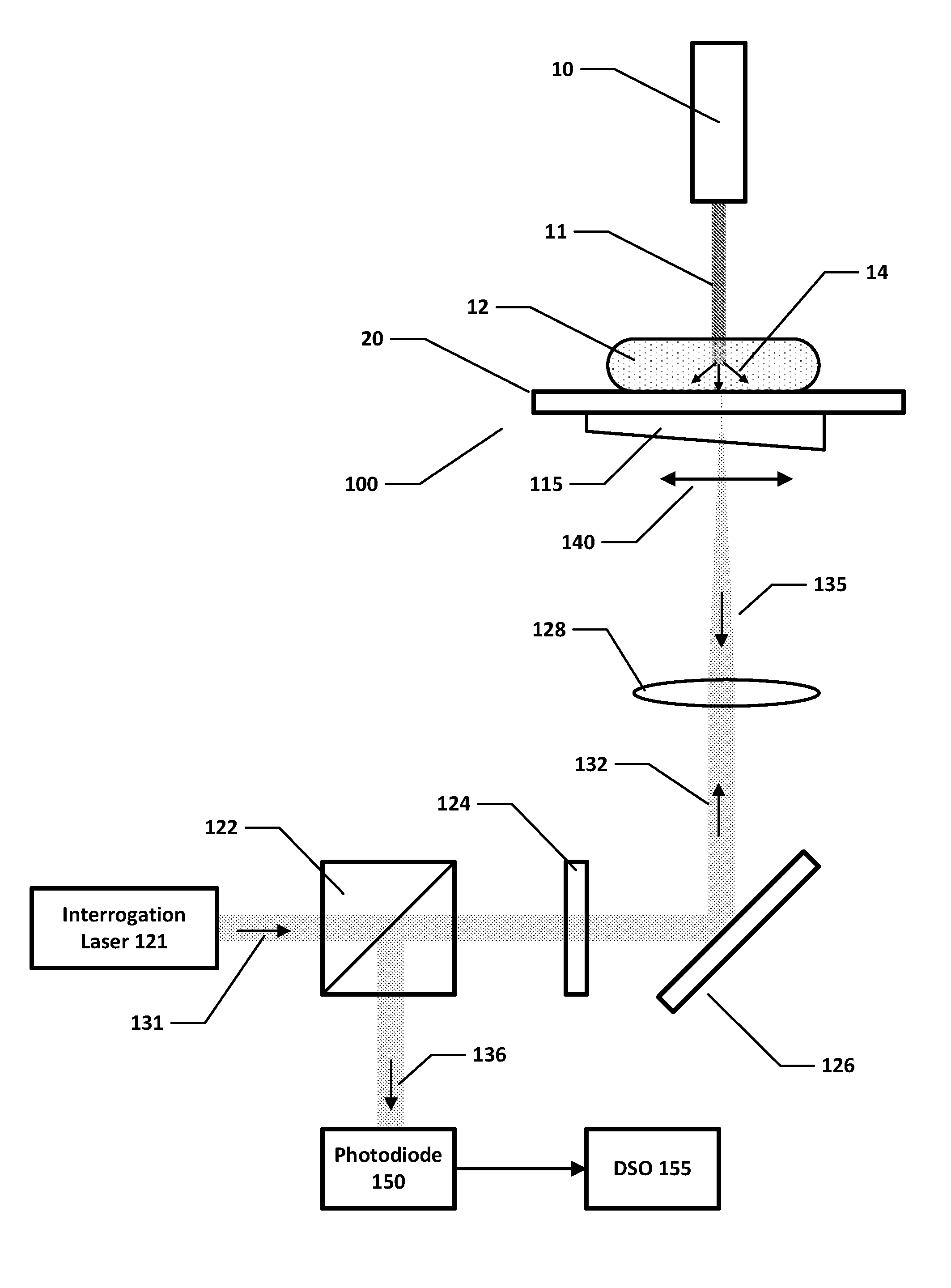
[0020]In PAT a short (ns) pulse of near-infrared or visible light is sent into tissue, whereupon absorption of photons generates a small local increase in pressure which propagates to the surface as a broadband ultrasound pulse. The amplitude of this signal is recorded at the tissue surface, such as by an array of sensors, and an image reconstruction algorithm is employed to estimate the original 3D pressure increase due to optical absorption—this is the photoacoustic image.

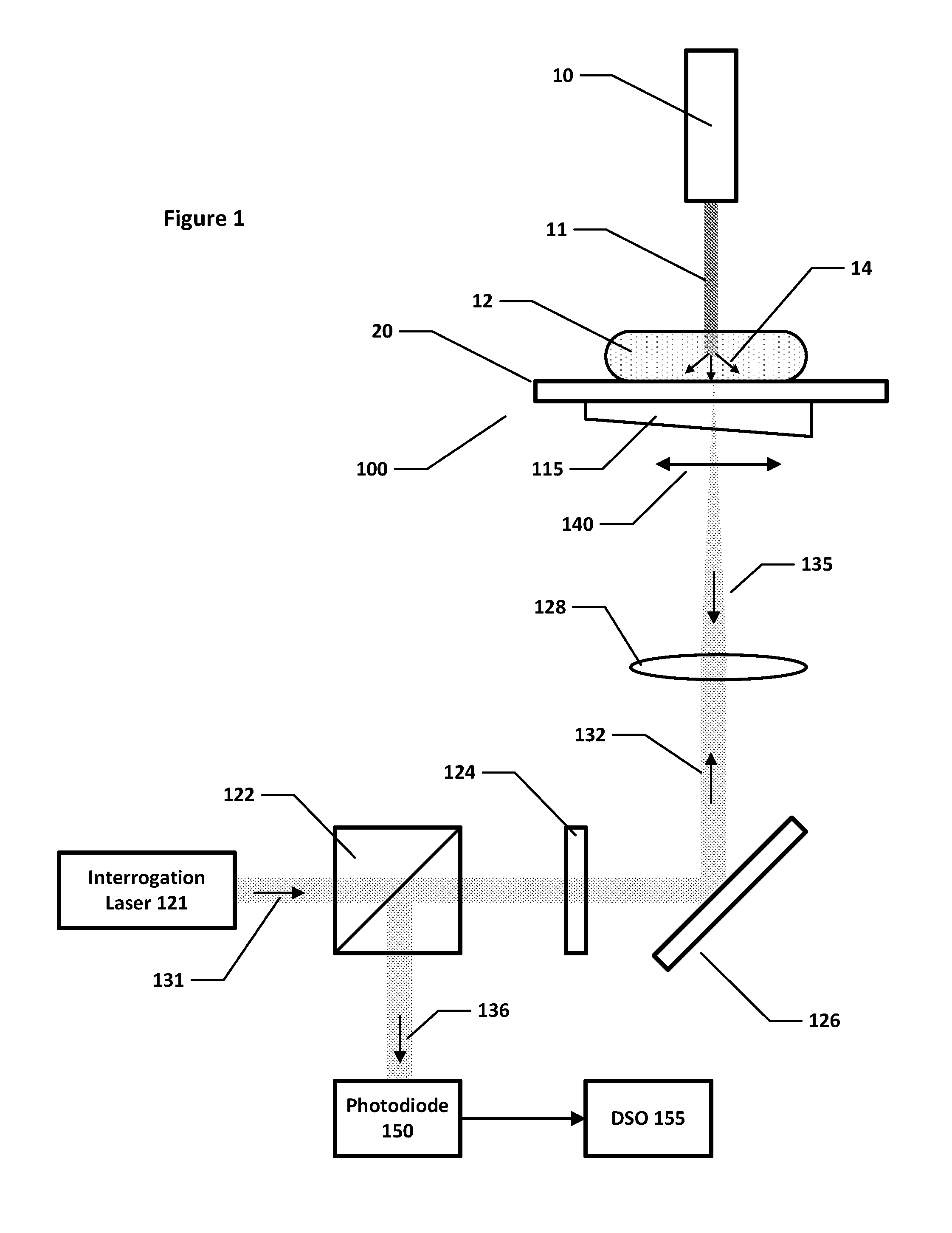
[0021]FIG. 1 is a schematic diagram of a PAT system including a Fabry-Perot interferometer detector 20 as described in the above-referenced paper by Zhang et al. A sample of tissue 12 being imaged is subjected to an excitation beam 11 comprising a pulse of electromagnetic radiation (optical, near infrared, or microwave) from excitation laser 10, which may be a multiple wavelength laser or a single wavelength laser. The output from excitation laser 10 typically falls within the wavelength range 400-2000 nm (althou...


PUM


Abstract

A method and apparatus are provided for performing photoacoustic tomography with respect to a sample that receives a pulse of excitation electromagnetic radiation and generates an acoustic field in response to said pulse. One embodiment provides an apparatus comprising an acoustically sensitive surface, wherein the acoustic field generated in response to said pulse is incident upon said acoustically sensitive surface to form a signal. The apparatus further comprises a source for directing an interrogation beam of electromagnetic radiation onto said acoustically sensitive surface so as to be modulated by the signal; means for applying a sensitivity pattern to the interrogation beam; and a read-out system for receiving the interrogation beam from the acoustically sensitive surface and for determining a value representing a spatial integral of the signal across the acoustically sensitive surface, wherein said spatial integral is weighted by the applied sensitivity pattern. The apparatus is configured to apply a sequence of sensitivity patterns to the interrogation beam and to determine a respective sequence of values for said weighted spatial integral for generating a photoacoustic image.

Description

FIELD OF THE INVENTION[0001]The present application relates to a method and apparatus for performing photoacoustic tomography, and in particular to providing such a method and apparatus having a reduced image acquisition time.BACKGROUND OF THE INVENTION[0002]Photoacoustic tomography (PAT) is an emerging biomedical imaging modality with both pre-clinical and clinical applications, and can provide complementary information to established imaging techniques [2, 30]. In the majority of such established imaging techniques, either the useful contrast mechanism is of low resolution, or high resolution images that are of limited contrast. PAT is an example of “imaging from coupled physics”, a new class of techniques, in which contrast induced by one physical mechanism is read by a different physical mechanism, so that both high resolution and high contrast can be obtained at the same time[0003]In PAT, ultrasound waves are excited by irradiating tissue with modulated electromagnetic radiatio...

Claims


Application Information

Patent Timeline
Patent Type & Authority Applications(United States)
IPC IPC(8): A61B5/00
CPCA61B5/7257A61B5/0095A61B8/13G01N29/0672G01N29/2418G01N2291/02475A61B5/7242A61B2576/00A61B5/7253G16H30/40
Inventor ZHANG, EDWARDBETCKE, MARTAARRIDGE, SIMONBEARD, PAULCOX, BEN
Owner UCL BUSINESS PLC
Why Eureka
Try Eureka