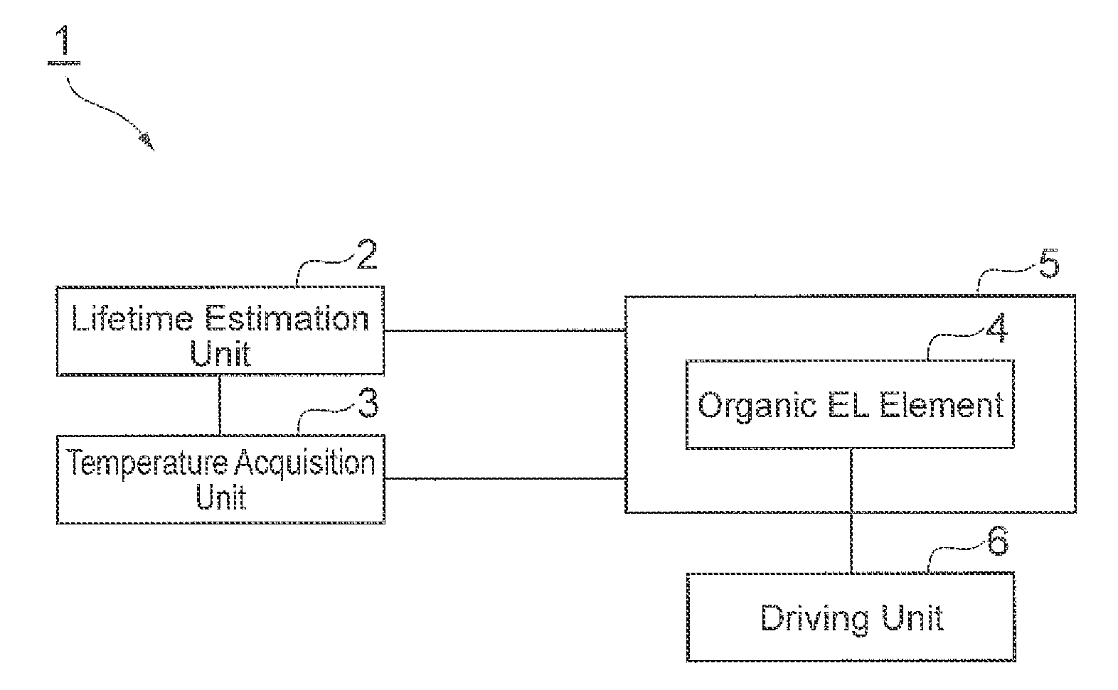
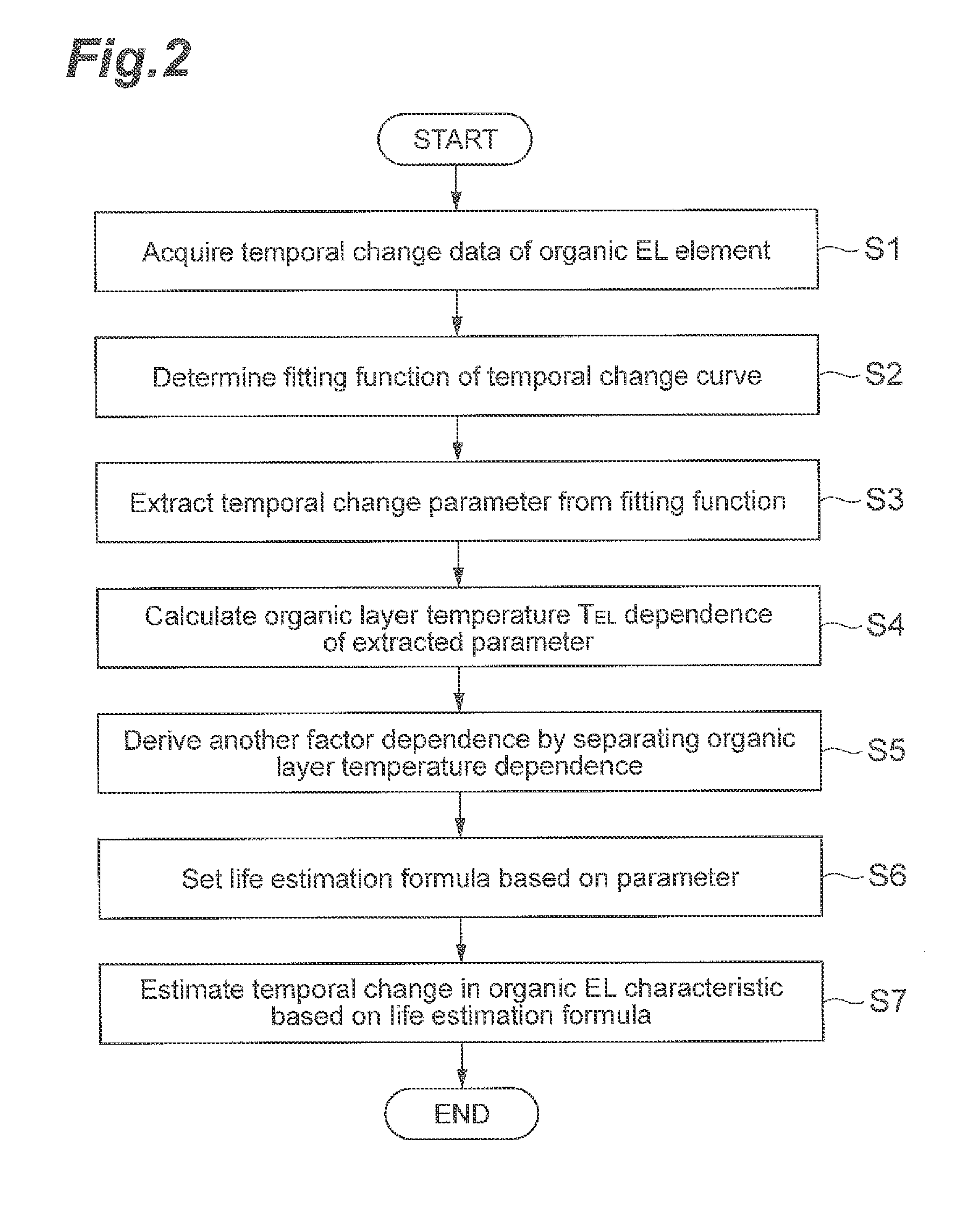
Method for Estimating Life of Organic EL Element, Method for Producing Life Estimation Device, and Light-Emitting Device
a technology of organic el and lifetime estimation, which is applied in the direction of heat measurement, semiconductor/solid-state device testing/measurement, instruments, etc., can solve the problems of increasing luminance, affecting the accuracy or convenience of measurement, and inability to perform measurement, so as to accurately estimate the lifetime of organic el. the effect of estimating the lifetime of the organic el elemen
- Summary
- Abstract
- Description
- Claims
- Application Information
AI Technical Summary
Benefits of technology
Problems solved by technology
Method used
Image

Examples
example
Example 1
[0133]First, the organic EL element was manufactured. Specifically, a hole injection layer and a hole transport layer were formed by a vacuum deposition process on a glass substrate on which ITO patterns were formed, and furthermore, an emission layer was formed by a vacuum deposition process using co-evaporation. Continuously, a hole blocking layer, an electron transport layer, and an electron injection layer were formed by a vacuum deposition process in a similar manner, and finally, a cathode made of aluminum was formed. Such a manufactured organic EL layer was sealed in a glove box that was held in an inert gas so as not to be exposed to atmosphere, thereby completing the organic EL element. A material used in each layer and a film thickness of each layer are shown in Table 1.
TABLE 1LayerconfigurationMaterialThicknessCathodealuminum (Al)150nmElectronlithium fluoride (LiF)1.6nminjection layerElectrontris(8-quinolinolato)aluminum (Alq3)30nmtransport layerHole blockingbis(...
example 2
[0149]With respect to the organic EL element manufactured in the same manner as Example 1, the lifetime test was performed by measuring the degradation in the luminance in the same manner as Example 1. An applied current density was n times a current density of 5 mA / cm2 (n=1, 2, 3, 5, 7, 10).
[0150]As a result of the lifetime test, the degradation in the luminance of the organic EL element at each current density became the degradation curve shown in FIG. 10. The degradation curve could be fit with a fitting function expressed by the following Formula (12). In Formula (12), b, γ, τ, and τ′ represent the degradation parameters. In the present Example, b was 0.7±0.05.
[Math.22]L(t)=L0·[γ·exp{-(tτ′)}+(1-γ)·exp{-(tτ)b}](12)
[0151]Then, when the elapsed time (a horizontal axis in FIG. 10) was normalized, a degradation curve as shown in FIG. 11 was acquired. The normalization of the elapsed time was performed by dividing the elapsed time by a time being a constant decay rate (for example, L(...
example 3
[0157]Subsequently, an Example of a method for acquiring a temperature of an organic EL element by using the temperature acquisition system shown in FIG. 17 is presented.
[0158]First, the organic EL element was manufactured. Specifically, a hole injection layer and a hole transport layer were formed by a vacuum deposition process on a glass substrate on which ITO patterns were formed, and furthermore, an emission layer was formed by a vacuum deposition process using co-evaporation. Continuously, a hole blocking layer, an electron transport layer, and an electron injection layer were formed by a vacuum deposition process in a similar manner, and finally, a cathode made of aluminum was formed. Such a manufactured organic EL layer was sealed in a glove box that was held in an inert gas so as not to be exposed to atmosphere, thereby completing the organic EL element. An emission area of the acquired organic EL element was 2 mm×2 mm. A material used in each layer and a film thickness of e...
PUM
| Property | Measurement | Unit |
|---|---|---|
| luminance | aaaaa | aaaaa |
| luminance | aaaaa | aaaaa |
| luminance | aaaaa | aaaaa |
Abstract
Description
Claims
Application Information
 - R&D
- Intellectual Property
- Life Sciences
- Materials
- Tech Scout
- Unparalleled Data Quality
- Higher Quality Content
- 60% Fewer Hallucinations
Browse by: Latest US Patents, China's latest patents, Technical Efficacy Thesaurus, Application Domain, Technology Topic, Popular Technical Reports.
© 2025 PatSnap. All rights reserved.Legal|Privacy policy|Modern Slavery Act Transparency Statement|Sitemap|About US| Contact US: help@patsnap.com