
Method for producing a key copy

a key copy and key technology, applied in the field of key manufacturing, to achieve the effect of reducing nois

Inactive Publication Date: 2016-04-28
BOSCH KARL HEINZ
View PDF4 Cites 33 Cited by
  • Summary
  • Abstract
  • Description
  • Claims
  • Application Information

AI Technical Summary

Benefits of technology

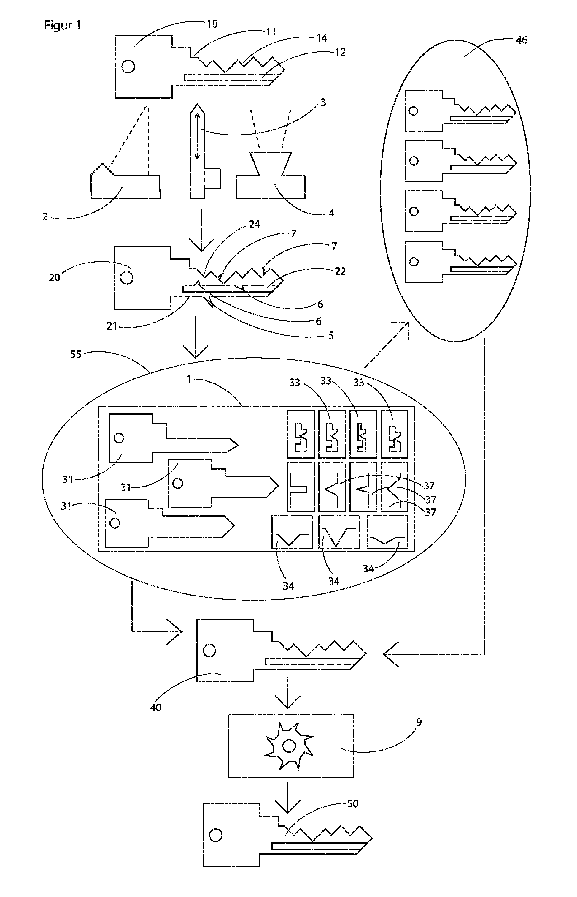
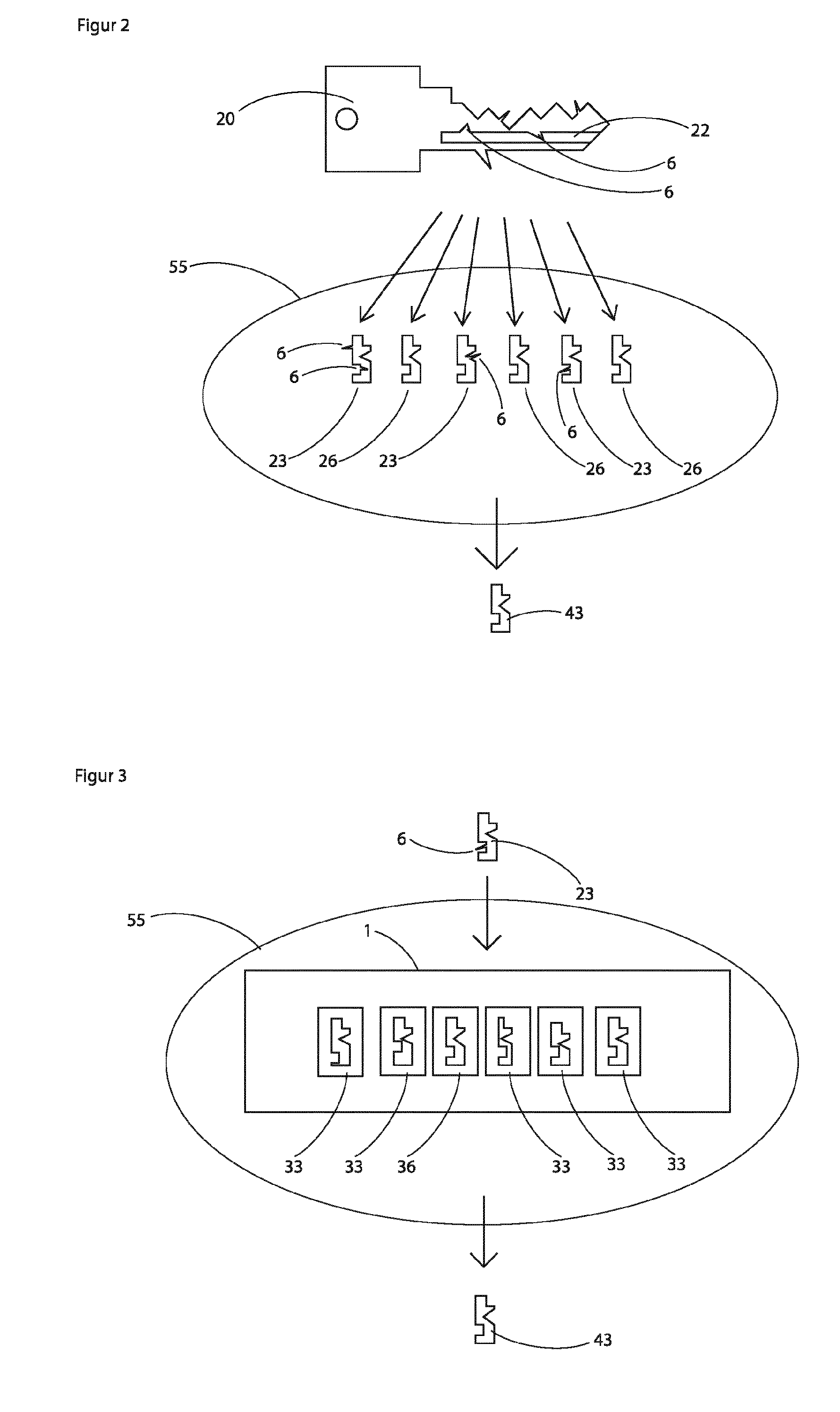
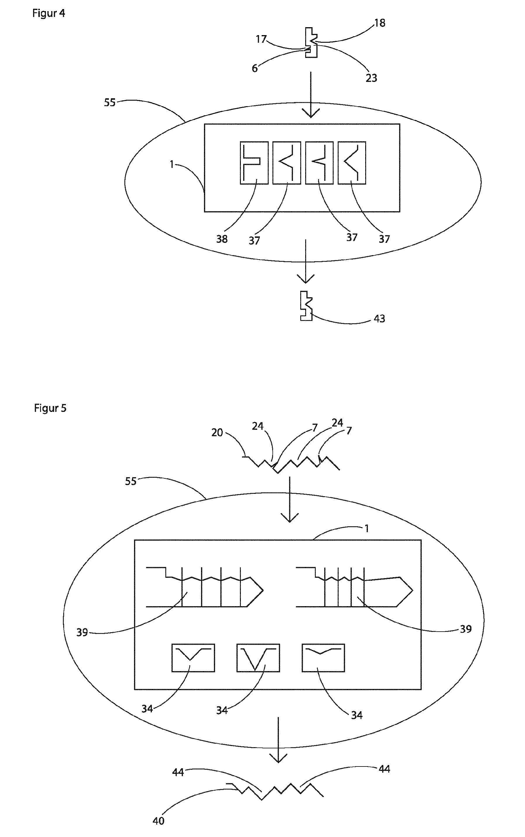
The invention provides a method for correcting errors in recorded data of a master key using data optimization. This method can reference data from a database of previously measured keys or from error-free copies of keys. By adding data from confirmed key copies, the database becomes more powerful. The method can also correct errors in partial areas of the recorded data using other error-free areas of the key. The processing unit carrying case can be closed during operation to dampen noise and prevent any chips or coolant from escaping.

Problems solved by technology

First, the required longitudinal profile is milled with a moulder in a key blank. Thereafter, the milled blank is unclamped, fixed in a vise and the length of the blade adjusted with a saw. Now the tip must be manually filed, or be processed with a grinding / milling machine. The thus prepared blank is clamped with the blade in a teeth milling machine and accurately aligned. In this milling machine, the teeth are then milled into the breast of the blank. For this purpose, suitable clamping jaws must be selected in order to fix the blank firmly enough in the machine. To mill teeth in the back, the key must be unclamped, rotated 180 degrees, re-clamped and aligned exactly. Now the teeth can only be milled in the back. Afterwards, the semi-finished key is unclamped from the teeth milling machine. In order to mill notches into the key, the key service requires a notch milling machine. A milling cutter suitable for the notches must be clamped, and the machine must be calibrated. The blade of the key, with the first broad side facing up, is clamped in the notch milling machine and precisely aligned. Since the key already has teeth, various, special clamping jaws are required to tighten the blade of the key well. Nevertheless, it often happens that the blade of the key slips during processing of the machine, and so the duplicate becomes unusable. By clamping the blade, only the upper broad side of the key is free for processing. After the milling of the notches in this broad side, the key must be unclamped, turned 180 degrees, and be clamped and aligned again. There is then the milling of the second broad side. Now the key is unclamped again, rotated 90 degrees, clamped to the blade, to provide the back with notches. This process for the notches of the breast may need to be repeated. Now the stop must still be manually adapted to the key in its thickness and width, or in a manual milling machine. For this purpose, it is again necessary to fix the already processed blade of the key well, which is complicated, because the key usually has no planar, parallel surfaces with which to fix it reliably. Finally, the key is clamped in an engraving machine to engrave the same inscription as the master key.
A disadvantage of this prior art is that the various individual processing machines, and the respective clamping devices are designed to clamp the key to its blade and align exactly to a stop.
The predominant part of the blade is concealed in the clamping device and cannot be reached by the milling tools, which makes frequent shifting necessary.
In addition, the processed blade usually has insufficiently planar surfaces on which the keys can be fixed with sufficient firmness.
The consequence is that the key often slips during milling, and so this key will not fit because the milled tumblers have incorrect dimensions, or are incorrectly positioned.
In addition, the risk is very high that the key is not made true to size, because the orientation of the key before the respective work steps is not performed perfectly accurately.
Another problem is that there is no common reference edge for gripping the key for the individual steps, because each machine has different clamping jaws.
So it often happens that the millings are not properly mounted relative to each other.
This leads to a very high price of the key.
So the machinery becomes larger every year and the operation of each machine is more complex.
A disadvantage of this method is that different milling cutters must be used for the manufacture of differently configured tumblers.
These parts are very expensive and complicated to use.
In addition, one needs cleaned compressed air for this and very complex machine control.
Due to this cost, the production of keys is uneconomical.
The corresponding milling spindle must have rotary axes for this, which additionally increases the cost of the machine.
In addition, all errors on the key copy that arise from recording are carried over.
Here, however, one does not receive information about the formation and the dimensions of the locking-relevant tumblers in the form of teeth or drill notches.
However, this process is unsuitable for obtaining the exact profile of the key blade because the depth and arrangement of the profile slots cannot be determined accurately enough.
In addition, it is very costly to extract the exact profile from the images of the key.
The profiles and configurations for the tumblers of modern keys continually become more varied, making the manufacture of key copies more difficult.
This complicates the manufacturing of key copies, since naturally the key copies must lie within these tight tolerances in order to function properly.
A disadvantage of this method is that the data arising from the recording of the surface of the master key, for technical reasons, has frequent mistakes, very high deviations, and missing areas.
The key copy directly manufactured from this data record then does not fit the lock cylinder or the lock.
If, for example, the recorded profile deviates in only one place from the required tolerance, the duplicate key manufactured therefrom cannot be introduced into the lock cylinder.
If only one tumbler, or part of a tumbler is outside of tolerance, the duplicate key will not be able to turn in the cylinder / lock.

Method used


Image

  • Method for producing a key copy
  • Method for producing a key copy
  • Method for producing a key copy

Examples


Embodiment Construction

[0064]FIG. 1 shows the method according to the invention as a simplified diagram. Here, the configuration of the surface of the key 10 is recorded with its outline contour 11, the tumblers 14 formed from cuts, and the profile 12 of the recording process in the form of laser line triangulation 2, the mechanical sensing elements 3 and / or of the camera 4. The data record 20 resulting from this recording has error 7 on the tumblers 24, error 6 on the profile 22, and error 5 on the outline contour 21. The errors are hereby detected by corresponding software, for example, where a plausibility check is carried out. By optimizing data 55, the faulty outline contour 21 of the data record 20 is compared manually or by means of software to the error-free outline contour 31 stored in the database 1, in order to determine the appropriate data record. Now error 5 can be corrected through the error-free points of the outline contour 31, or the complete, error-free outline contour 31 can be used ag...


PUM

PropertyMeasurementUnit
depthsaaaaaaaaaa
widthaaaaaaaaaa
thicknessaaaaaaaaaa

Abstract

A method for producing a key (50), wherein a data set (40) of a key is obtained by recording the surface of the key (10) and subsequently performing a data optimization (55), or from data of a data collection (46), in order to produce the key (50) from a semi-finished product clamped in a machine by a computer-controlled production method (9), wherein at least two different locking features are introduced into the semi-finished product.

Description

BACKGROUND OF THE INVENTION[0001]The present invention relates to a method for manufacturing a key.[0002]In order to manufacture or duplicate a key, preferably fitting a lock cylinder of a master key system, all lock-relevant characteristics of the key must match the master key, or the lock. These characteristics are essentially: The width, thickness, length, back rounding and tip shape of the key blade, the profile in the longitudinal direction of the blade, the thickness and breadth of the stop, the tumblers in the form of jagged cuts in the key breast and in the key back, tumblers in the form of notches or tracks on the two broad sides, the back and the breast of the key blade. To manufacture a key in accordance with a master key, or to fit a lock, key services need to perform many operations, and require a large number of individual machines and tools for this. According to the prior art, the following steps for manufacturing a conventional key are necessary:[0003]First, the req...

Claims


Application Information

Patent Timeline
Patent Type & Authority Applications(United States)
IPC IPC(8): B23C3/35G06T7/00G01B11/30G06F17/30B23Q35/40B23Q35/26G06V10/46
CPCB23C3/35B23Q35/40B23Q35/26G01B11/303G06F17/30247G06F17/30303G06T2207/30108B23C2235/04B23C2235/12B23C2235/41B23C2235/48B23C2250/12G06T2207/10004G06T7/0004B23C5/10B23P15/005B23C2235/32G01B21/20B23Q3/15546B23Q11/1007B23Q35/32G01B11/24B23Q37/007G06F16/215G06F16/583G06V10/10G06V10/46G06V20/66
Inventor BOSCH, KARL-HEINZ
Owner BOSCH KARL HEINZ
Learn More