Device and method for generative component production

Active Publication Date: 2016-04-28
FRAUNHOFER GESELLSCHAFT ZUR FOERDERUNG DER ANGEWANDTEN FORSCHUNG EV
View PDF2 Cites 34 Cited by
  • Summary
  • Abstract
  • Description
  • Claims
  • Application Information

AI Technical Summary

Benefits of technology

The suggested device and method described in this patent offer a more efficient and cost-effective way to produce powder-based products using selective laser melting. By simultaneously applying powder and exposing it to laser beams, the device can significantly reduce processing times and provide improved quality. Compared to previous systems, the suggested device is significantly smaller and can use more cost-effective laser sources. Additionally, the method can use the same beam sources for both processing and surface treatment, improving the efficiency of the process. The device can also be used with smaller laser power and can be easily scaled by increasing the number of beam sources.

Problems solved by technology

However, for a broad industrial use of such a production method, higher build-up rates, shorter auxiliary processing times and larger installation spaces are primarily required.
When increasing the laser power, however, material vaporisation occurs due to the high intensity at the processing location, which results in high splatter and soot formation and also deep-penetration welding, which leads to an unstable process and correspondingly poor component quality.
However, this leads to a reduction of the surface quality and detail resolution.
However, a higher build-up rate can only be achieved using this technology for solid components with significant core volumes.
When using higher laser powers, the high scanning speeds of >2 m / s required therefor also can no longer be achieved constantly, due to the inertia of the scanner mirrors.
This results in a clear thermal shift of the focus position in the size of the Rayleigh length.
However, the scanning field of the scanners used is fundamentally limited by the maximum angle of rotation of the mirrors and also via the focal length of the focussing lens used.
However, this necessitates the development of novel scanning strategies for building up components in a defect-free manner in the overlap region of the individual scanning fields and means a significantly higher cost portion for optical components in larger installation spaces.
This auxiliary processing time scales in conventional selective laser melting with the number of layers and the dimensioning of the installation space in the powder application direction and cannot be used for the exposure.

Method used


Image

  • Device and method for generative component production
  • Device and method for generative component production
  • Device and method for generative component production

Examples


Embodiment Construction

[0009]The object is achieved with the device and the method according to the Patent Claims 1 and 13. Advantageous configurations of the device as well as of the method are the subject matter of the dependent patent claims or can be drawn from the following description as well as from the exemplary embodiments.

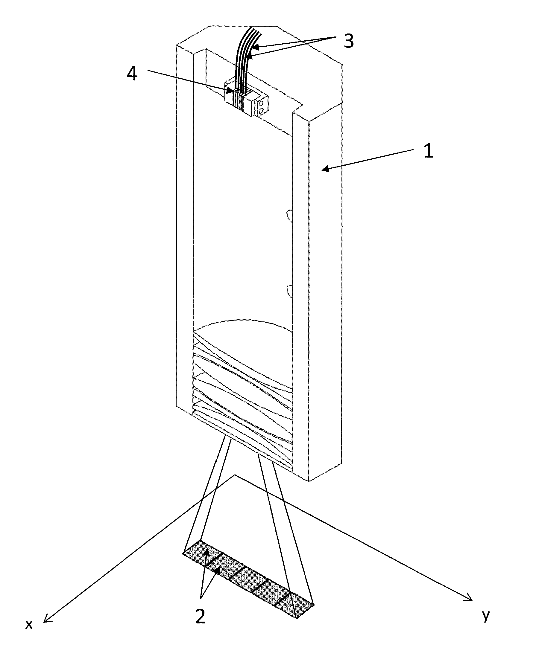
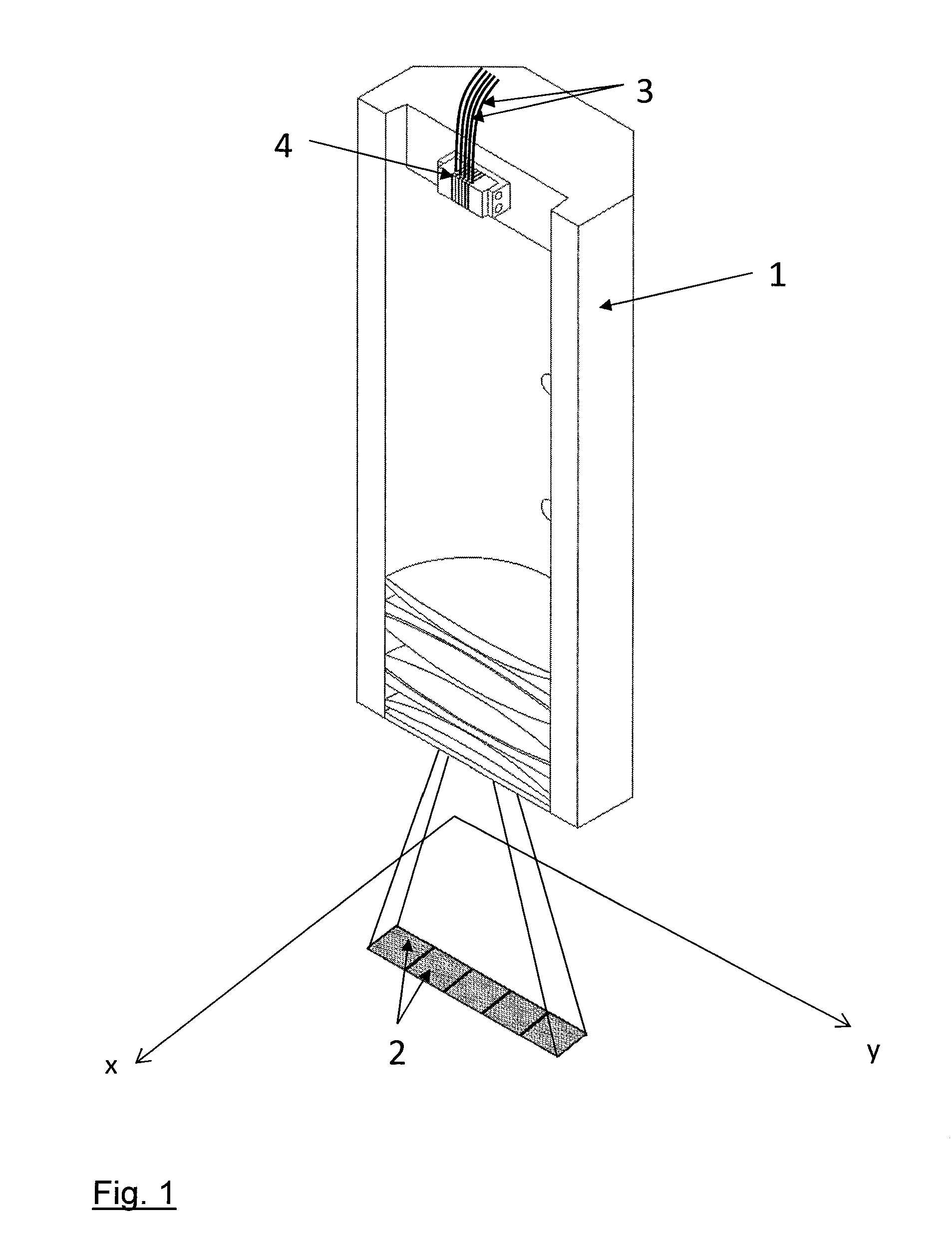
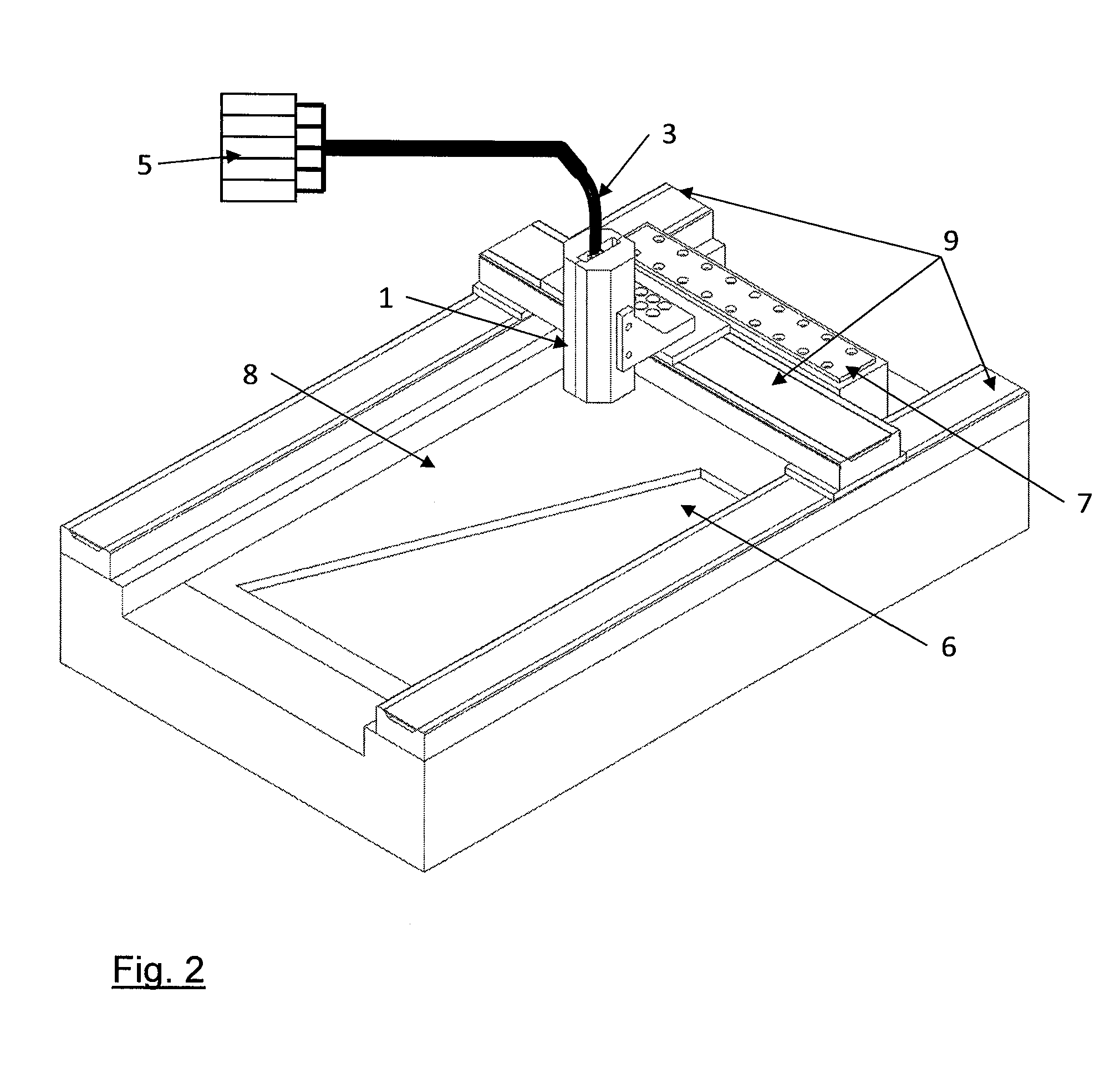
[0010]The suggested device for generative component production has a processing head, using which a plurality of mutually separate laser beams are directed adjacently and / or overlapping to some extent onto the processing plane, in which the workpiece to be processed is provided. The device furthermore comprises a laser beam source arrangement, using which the mutually separate laser beams can be generated, a movement apparatus, which can generate a relative movement between processing head and processing plane in mutually parallel planes, particularly by moving the processing head across the processing plane, an apparatus for providing the material for the component in the proc...


PUM

PropertyMeasurementUnit
Lengthaaaaaaaaaa
Sizeaaaaaaaaaa
Widthaaaaaaaaaa

Abstract

The present invention relates to a device for laser-based generative component production. The device comprises a processing head (1), using which a plurality of mutually separate laser beams are directed adjacently and / or overlapping to some extent onto the processing plane, The processing head (1) is moved across the processing plane using a movement apparatus (9), whilst the mutually separate laser beams are modulated independently of one another in terms of intensity, in order to obtain the desired exposure geometry. The laser power and the dimensional size can be scaled cost effectively during the generative production using the suggested device and the associated method.

Description

TECHNICAL FIELD OF APPLICATION[0001]The present invention relates to a device and a method for laser-based generative component production.[0002]One example for a laser-based generative production method is selective laser melting (SLM), using which functional components can be produced in layers. Selective laser melting and similar generative production methods offer the possibility to produce components with complex (internal) geometries, which cannot be produced using conventional production methods, such as for example machining or casting methods.[0003]During selective laser melting, the component is divided into layers (typ. <100 μm) starting from a 3D CAD model by means of specialist software. The thereby-generated component information is then provided to the SLM system via standardised data formats and is used as a basis of the production process. A fine-grained powder material, the d50 particle size of which is preferably <100 μm, is generally used as base material. ...

Claims


Application Information

Patent Timeline
IPC IPC(8): B23K26/08B23K26/342B23K26/144B22F3/105
CPCB23K26/0876B22F3/1055B22F2003/1057B23K26/144B23K26/342B23K26/0608B23K26/354B29C64/153B29C64/268B29C64/277Y02P10/25B22F10/28B22F10/36B22F10/322B22F12/47B22F12/44B22F12/45
Inventor EIBL, FLORIANHAGEDORN, YVES-CHRISTIANJAUER, LUCASMEINERS, WILHELM
Owner FRAUNHOFER GESELLSCHAFT ZUR FOERDERUNG DER ANGEWANDTEN FORSCHUNG EV
Why Eureka
Try Eureka