Method and Apparatus for a Directly Electrically Heated Flow-Through Chemical Reactor

a flow-through chemical reactor and flow-through technology, which is applied in lighting and heating apparatus, separation processes, combustion types, etc., can solve the problems of non-uniform heat distribution to the chemical substance, harm to the environment, and deformation of ozone gas into oxygen, so as to reduce size and/or cost, the effect of uniform heat distribution and short heating tim

Inactive Publication Date: 2016-04-28
MKS INSTR INC
View PDF3 Cites 8 Cited by
  • Summary
  • Abstract
  • Description
  • Claims
  • Application Information

AI Technical Summary

Benefits of technology

[0012]One advantage of the invention is that heating, reacting and housing of chemical substances can all be achieved with the same structural component (e.g., the electrically conductive member). Heating the chemical mixture by heating the chemical reactor allows for elimination of a separate heating element. As such, another advantage of the invention is reduced size and / or cost.
[0013]Other advantages of the invention include a more uniform heat distribution and a shorter heating-up time. These advantages are achieved by eliminating the heating element that creates additional resistance in the system. Another advantage of the invention is that the system has improved chemical resistance and / or can operate over a range of chemical substances because the chemical reactor alone, and not a separate heating element, is subject to the chemical substance. Another advantage of the invention is that, for ozone destruct applications, the ozone conversion from ozone gas into oxygen can be greater than 95% because of more uniform heat distribution and quicker heat up time. Another advantage of the invention is the minimization of condensation build-up due to substantially complete uniform heated chemical reactor and the elimination of dead volumes by the one tube design of the reactor.
[0014]In one aspect, the invention involves a method of facilitating a chemical reaction. The method involves directly coupling an electrically conductive member and a source of electrical power, the electrically conductive member having an interior region configured to be substantially resistant to chemical corrosion and capable of retaining a chemical mixture therein. The method also involves providing the chemical mixture to the interior region of the electrically conductive member. The method also involves heating the electrically conductive member to a predetermined temperature by controlling the electrical power applied to the electrically conductive member to cause a chemical reaction within the chemical mixture.
[0015]In some embodiments, the chemical reaction is ozone destruction. In some embodiments, the method further involves heating the electrically conductive member to a predetermined temperature that is greater than 200 degrees Celsius. In some embodiments, selecting the predetermined temperature based on the chemical mixture, the type of electrically conductive member, or any combination thereof.
[0016]In some embodiments, the method involves cooling a section of the electrically conductive member to cool the chemical mixture upon exiting the electrically conductive member. In some embodiments, the electrically conductive member is a metallic tube. In some embodiments, the electrically conductive member is single structure that is electrically and thermally conductive.
[0017]In another aspect, the invention involves a system for facilitating a chemical reaction. The system includes a metallic tube that is substantially resistant to chemical corrosion and capable of retaining a chemical mixture therein, the metallic tube having a first section and a second section. The system also includes a power source directly electrically coupled to the metallic tube, the power source being configured to heat the first section of the metallic tube. The system also include a controller electrically coupled to the power source, the controller controls power to the metallic tube such that when the chemical mixture flows into the metallic tube the chemical mixture is heated to cause a chemical reaction within the chemical mixture.

Problems solved by technology

It can be harmful to release ozone gas into the environment, making it desirable to destruct the ozone excess gas.
The application of heat can cause the ozone gas to be destructed into oxygen.
One problem with system 100 is that the tube 120 may need to be welded or otherwise manipulated (e.g., bent) causing the heat distribution to the chemical substance to be non-uniform.
In addition, portions of the tube 120 can have unwanted condensation build-up and dead-ends, further contributing non-uniform heat distribution.
Current methods can also have a longer than desirable heat-up time due to, for example, additional heat resistance caused by the presence of a heating element.
Current methods and apparatus' can be very expensive, large, and / or heavy due to, for example, size, cost and / or weight of a heating element
Another problem is that existing thermal reactors typically do not have good chemical resistance and / or cannot operate over a range of chemical substances, due to, for example, the inability of heating elements to withstand chemicals having a high corrosion.
Poor chemical resistance can result in premature corrosion of a reactor.
Another problem with current methods is that for ozone destruction, the ozone conversion rate from ozone gas into oxygen can be less than 95%.

Method used


Image

  • Method and Apparatus for a Directly Electrically Heated Flow-Through Chemical Reactor
  • Method and Apparatus for a Directly Electrically Heated Flow-Through Chemical Reactor
  • Method and Apparatus for a Directly Electrically Heated Flow-Through Chemical Reactor

Examples


Embodiment Construction

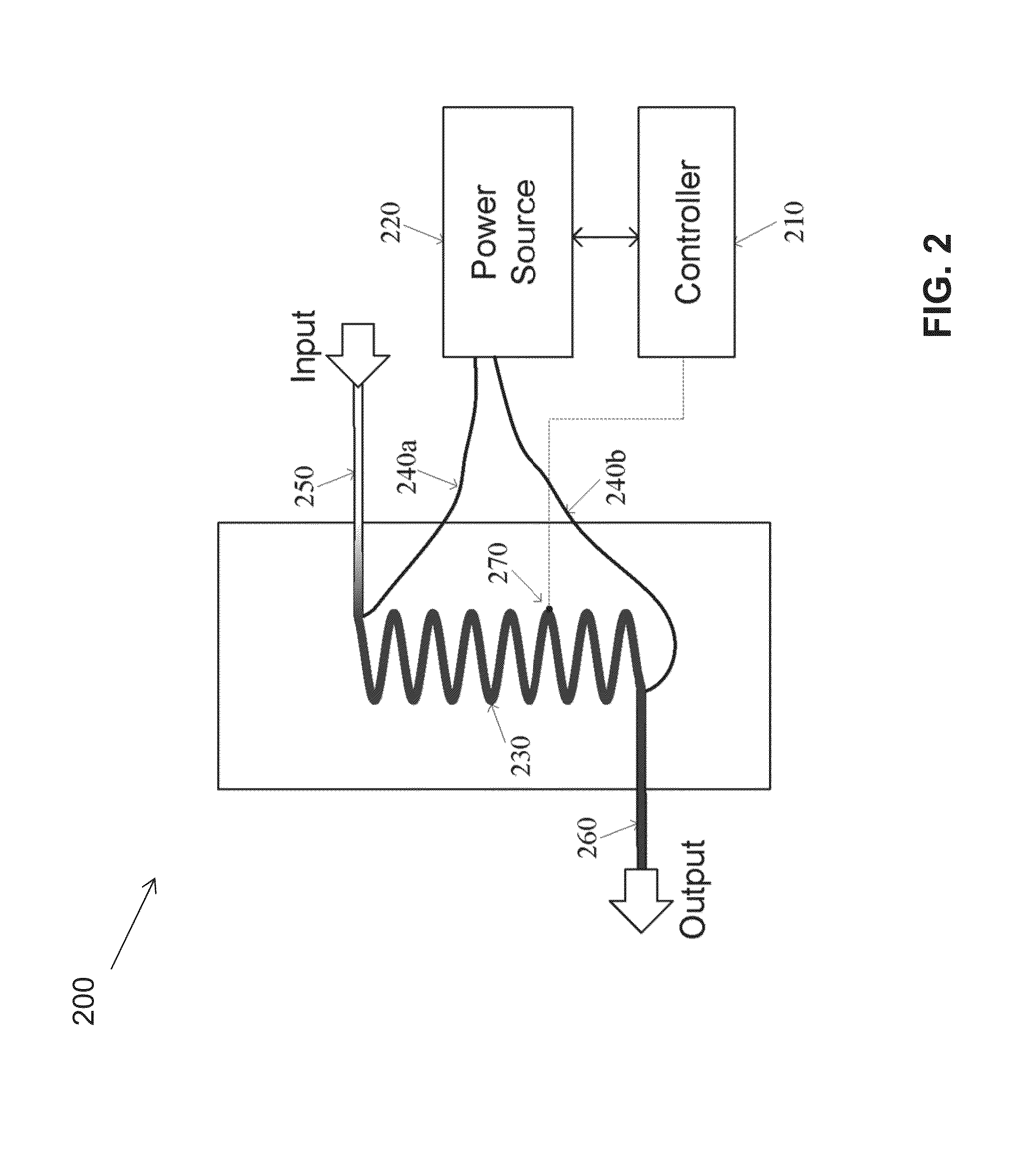
[0029]Generally, the invention includes directly coupling an electrically conductive member (e.g., a metallic tube) and a power source. The electrically conductive member is capable of retaining a chemical mixture therein. The power source applies power to the electrically conductive member. The electrically conductive member heats up as a result of the applied power. The electrically conductive member has an interior region that allows for a chemical mixture to flow therethrough.

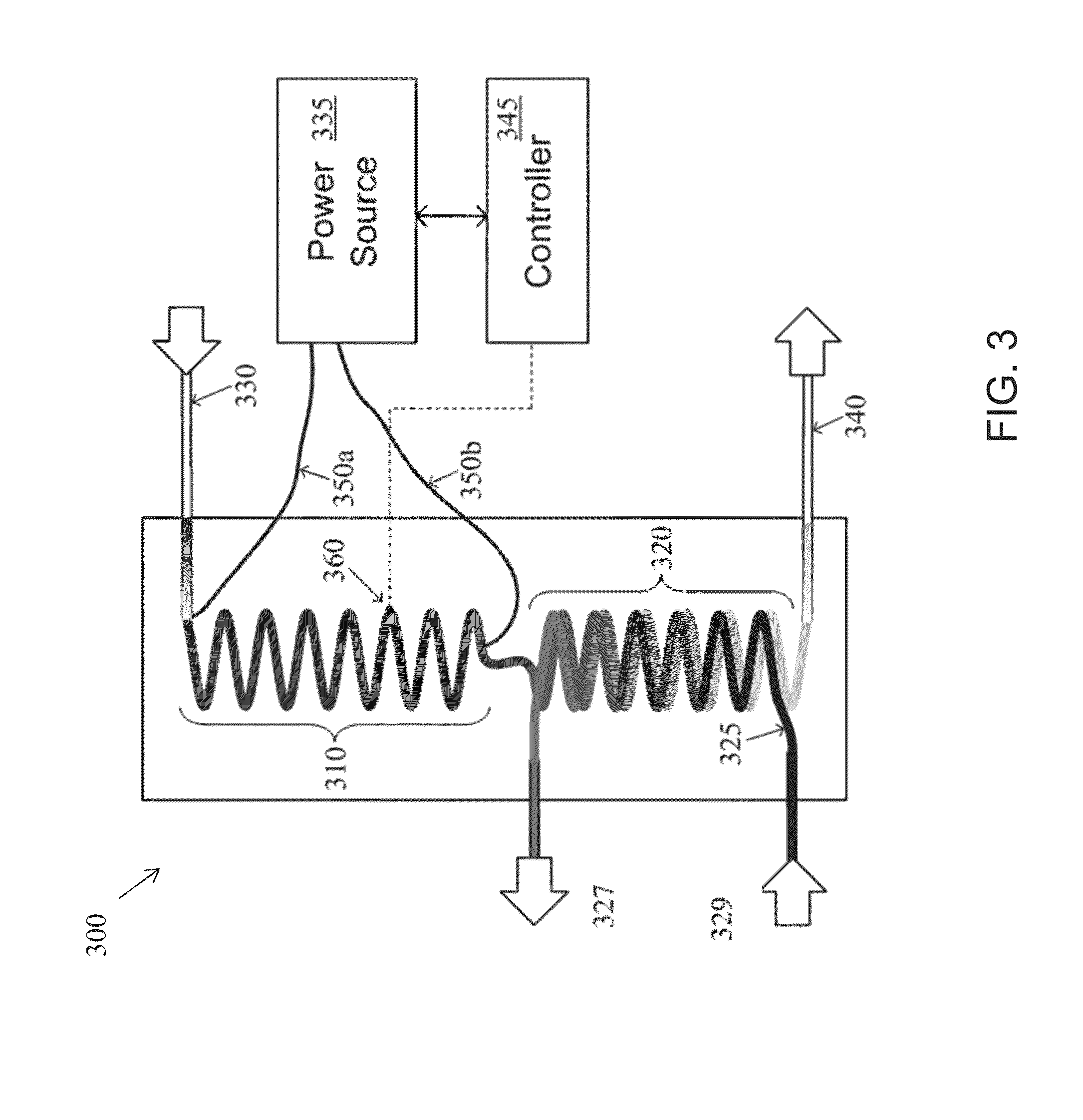
[0030]When a chemical mixture is disposed within the interior region of the electrically conductive member and power is applied, the heat generated in the electrically conductive member transfers to the chemical mixture causing the chemical mixture to be heated. A portion of the electrically conductive member can be cooled. The cooled portion of the electrically conductive member can cool the chemical mixture flowing through the electrically conductive member. The chemical mixture can be cooled, in one embo...


PUM

PropertyMeasurementUnit
temperatureaaaaaaaaaa
temperaturesaaaaaaaaaa
lengthaaaaaaaaaa

Abstract

A system and method for facilitating a chemical reaction is provided. The system can have an electrically conductive member. The electrically conductive member is capable of holding a chemical mixture. The electrically conductive member is directly coupled to a power source and is heated when the power source is on. When a chemical mixture is within the electrically conductive member and the power source is on, the chemical mixture is heated such that a chemical reaction can occur.

Description

CROSS REFERENCE TO RELATED APPLICATIONS[0001]This application is a division of U.S. Ser. No. 14 / 189,649, filed on Feb. 25, 2014, which claims benefit of and priority to U.S. Ser. No. 61 / 956,189, filed on Feb. 14, 2014. These applications are owned by the assignee of the instant application and the disclosures of each of these applications are incorporated herein by reference in their entireties.FIELD OF THE INVENTION[0002]This invention relates generally to devices, systems, and methods employed in chemical vapor deposition (CVD) and wet wafer processing applications. In particular, the invention relates to directly coupling a conductive member to an electrical power source to heat the conductive member in order to create a chemical reaction from one or more chemical substances disposed within the conductive member.BACKGROUND OF THE INVENTION[0003]When manufacturing semiconductor devices, a variety of chemicals are used. Chemical substances can be used to etch wafers, clean chambers...

Claims


Application Information

Patent Timeline
Patent Type & Authority Applications(United States)
IPC IPC(8): C01B13/02
CPCC01B13/02B01D53/66B01J19/2415B01J19/243B01D2257/106B01D2257/2066B01D2258/0216B01J2219/0277B01J2219/0286B01J2219/00132B01J2219/00135B01J2219/00159A62D3/40F23G5/10C01B13/0203B01J19/0013
Inventor SEIWERT, JOHANNESGOTTSCHALK, CHRISTIANELOHR, JOACHIMBLACHA, MARTIN
Owner MKS INSTR INC
Why Eureka
Try Eureka