
Article and method of making thereof

a technology of protective coatings and articles, applied in the field of articles, can solve the problems of reducing the coating, reducing the coating, and reducing the coating,

Active Publication Date: 2016-04-28
GENERAL ELECTRIC CO
View PDF9 Cites 26 Cited by
  • Summary
  • Abstract
  • Description
  • Claims
  • Application Information

AI Technical Summary

Benefits of technology

This patent describes an article with a thermal barrier coating and a protective coating that contains a material that can react with a certain composition at high temperatures to form a more viscous and solid reaction product. This helps to improve the performance of the coated article in high-temperature environments. The invention is particularly useful for turbine engine components. The coated components can withstand higher temperatures, leading to improved engine performance. The method of manufacturing the coated components involves placing a thermal barrier coating on a substrate and then adding a protective coating containing the material that reacts with CMAS. This results in a reaction product that has higher melting temperature and viscosity than the original CMAS composition.

Problems solved by technology

Under normal conditions of operation, thermal-barrier coated components may be susceptible to various types of damage, including erosion, oxidation, and attack from environmental contaminants.
These oxides combine to form contaminant compositions comprising mixed calcium-magnesium-aluminum-silicon-oxide systems (Ca--Mg--Al--SiO), hereafter referred to as “CMAS.” At the high turbine operating temperatures, these environmental contaminants can adhere to the heated or hot thermal barrier coating surface, and thus cause damage to the thermal barrier coating.
Upon cooling, the infiltrated CMAS composition solidifies and reduces the coating strain tolerance, thus initiating and propagating cracks that may cause delamination and spalling of the coating material.
This may further result in partial or complete loss of the thermal protection provided to the underlying metal substrate of the part or component.
Further, spallation of the thermal barrier coating may create hot spots in the metal substrate leading to premature component failure.
Premature component failure can lead to unscheduled maintenance as well as parts replacement resulting in reduced performance, and increased operating and servicing costs.

Method used


Image

  • Article and method of making thereof
  • Article and method of making thereof
  • Article and method of making thereof

Examples


example 1

Reaction of CMAS with NZP-type Materials

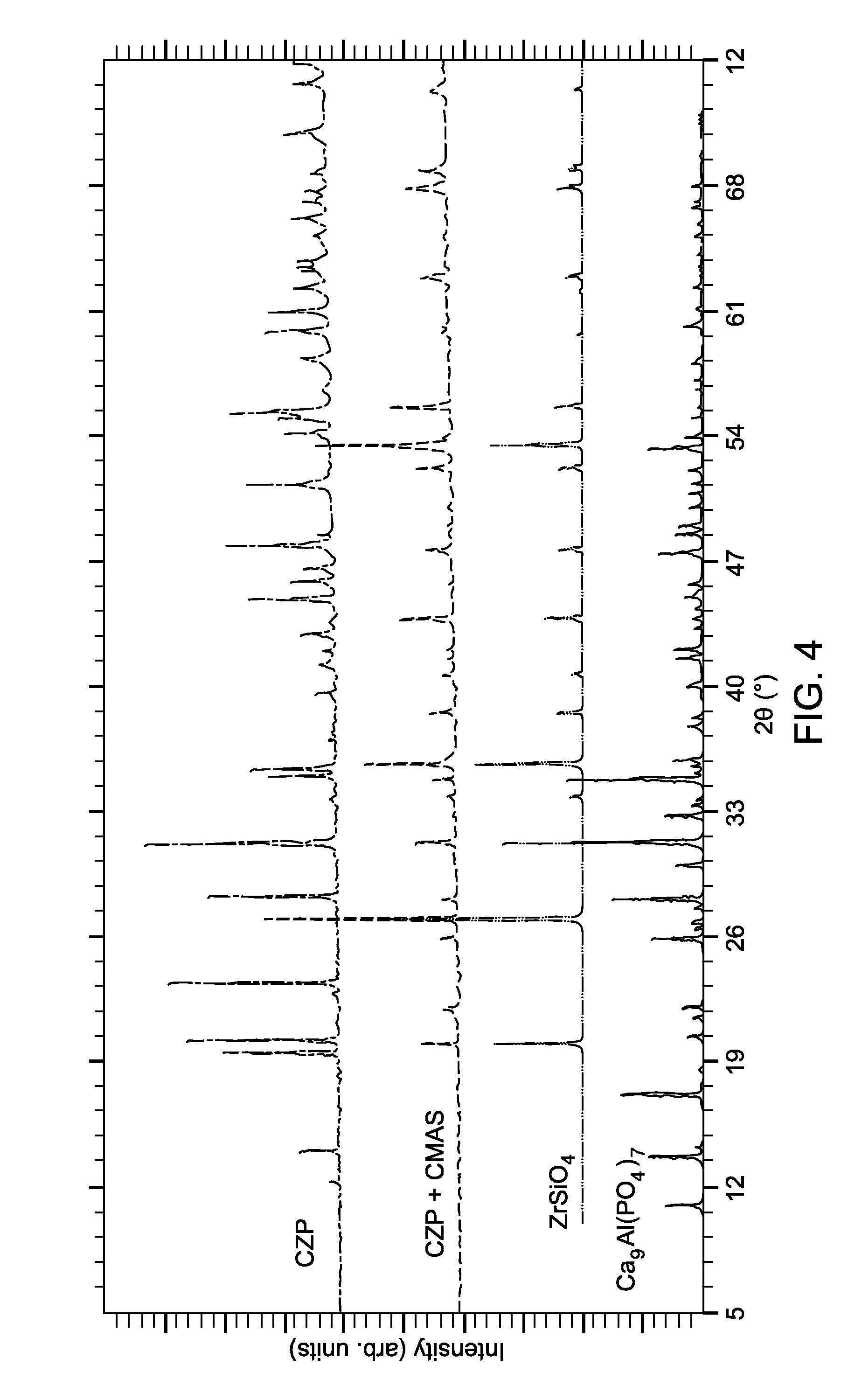
[0066]The three different NZP-type materials (as pellets) were contacted with CMAS composition at 1400° C. for 15 minutes. The weight ratio of NZP-type material to the CMAS composition was 1:1. All the three NZP-type materials reacted completely with CMAS forming ZrSiO4 and Ca9Al(PO4)7 as major type of phases. FIGS. 4-6 show the PXRD patterns for reaction products of CZP, CSZP and SZP with CMAS, along with reference patterns for ZrSiO4 and Ca9Al(PO4)7.


PUM

PropertyMeasurementUnit
thicknessaaaaaaaaaa
melting temperatureaaaaaaaaaa
operational temperaturesaaaaaaaaaa

Abstract

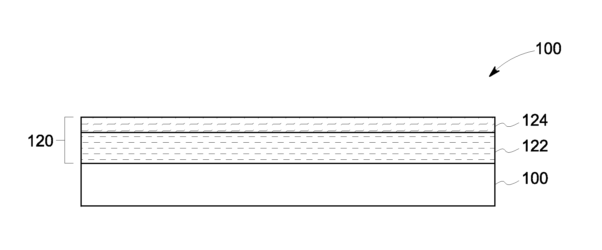
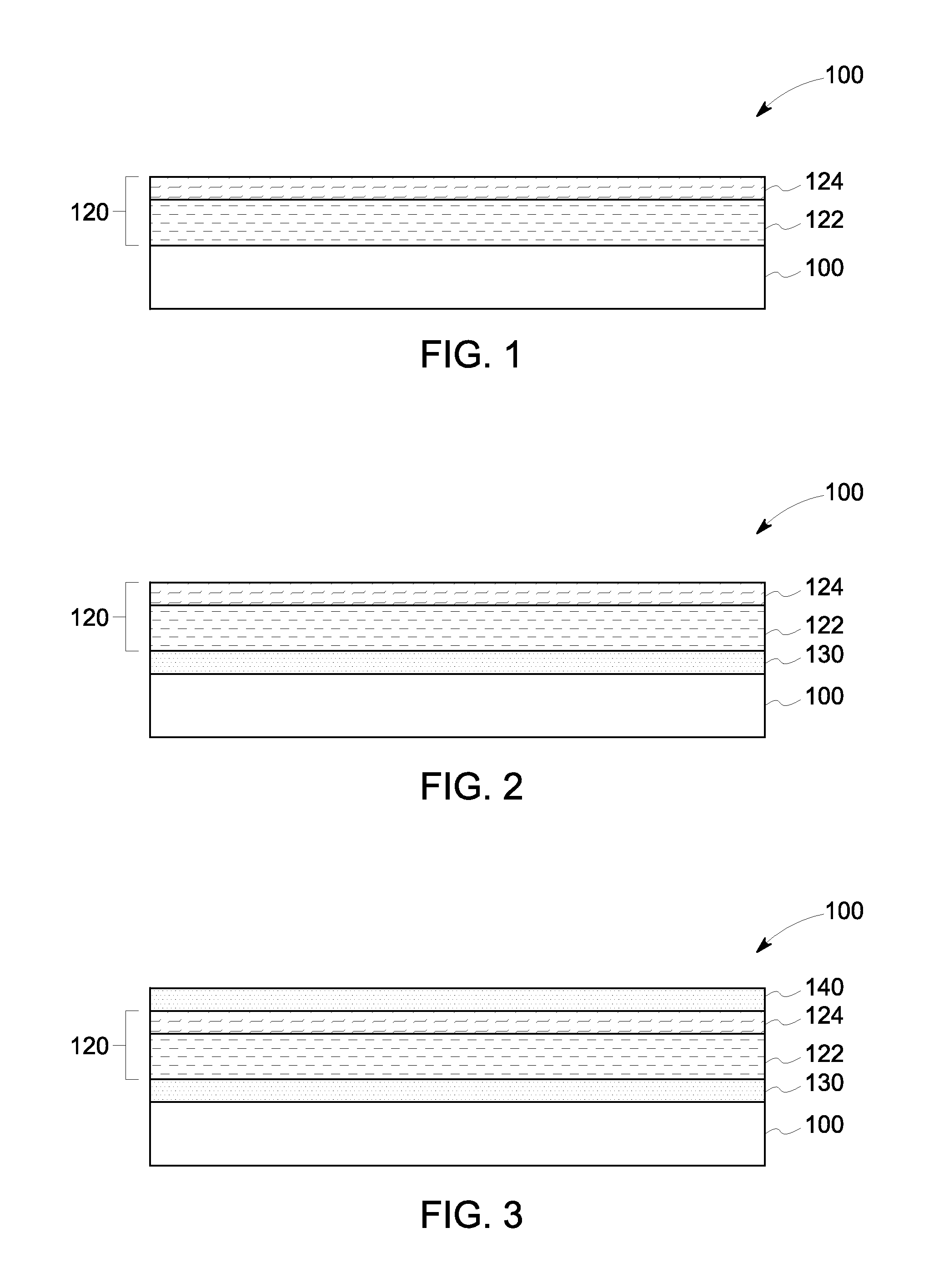
An article including a substrate and a plurality of coatings disposed on the substrate is presented. The plurality of coatings includes a thermal barrier coating disposed on the substrate; and a protective coating including a calcium-magnesium-aluminum-silicon-oxide (CMAS)-reactive material disposed on the thermal barrier coating. The CMAS-reactive material includes an NZP-type material. The CMAS-reactive material is present in the plurality of coatings in an effective amount to react with a CMAS composition at an operating temperature of the thermal barrier coating, thereby forming a reaction product having one or both of melting temperature and viscosity greater than that of the CMAS composition. A method of making the article and a related turbine engine component are also presented.

Description

BACKGROUND OF THE INVENTION[0001]The invention relates generally to articles including protective coatings for thermal barrier coatings. More particularly, the invention relates to articles including protective coatings for thermal barrier coatings, such that the protective coatings are calcium-magnesium-aluminum-silicon-oxide (CMAS)-reactive.[0002]Thermal barrier coatings are typically used in articles that operate at or are exposed to high temperatures. Aviation turbines and land-based turbines, for example, may include one or more components protected by the thermal barrier coatings. Under normal conditions of operation, thermal-barrier coated components may be susceptible to various types of damage, including erosion, oxidation, and attack from environmental contaminants.[0003]For turbine components, environmental contaminant compositions of particular concern are those containing oxides of calcium, magnesium, aluminum, silicon, and mixtures thereof. These oxides combine to form...

Claims


Application Information

Patent Timeline
Patent Type & Authority Applications(United States)
IPC IPC(8): F01D25/00C23C14/22C23C14/08C23C4/12
CPCF01D25/005C23C14/08C23C14/22C23C4/127C04B35/16C04B35/447C04B2235/3201C04B2235/3208C04B2235/3217C04B2235/3225C04B2235/3227C04B2235/3229C04B2235/3244C04B2235/3248C04B2235/3418C04B2235/80C23C14/06C23C28/042C23C28/321C23C28/3215C23C28/3455F05D2300/6111C04B35/00C23C4/126C23C4/129C23C4/131C23C4/134Y02T50/60
Inventor POROB, DIGAMBER GURUDASSIVARAMAKRISHNAN, SHANKARVENKATARAMANI, VENKAT SUBRAMANIAMNAYAK, MOHANDASRAMACHANDRAN, GOPI CHANDRAN
Owner GENERAL ELECTRIC CO
Learn More