
Heat receiving tile formed of carbon fiber composite material and method of manufacturing the same

Inactive Publication Date: 2016-04-28
ATOX
View PDF0 Cites 8 Cited by
  • Summary
  • Abstract
  • Description
  • Claims
  • Application Information

AI Technical Summary

Benefits of technology

The present invention provides a heat receiving tile made of carbon fiber composite material that has a high heat flux component, such as a divertor of a nuclear fusion reactor. The heat receiving tile has improved heat removal efficiency compared to conventional heat receiving tiles. The method of assembly, manufacturing procedure, and test results of the heat receiving tile are described in detail in the patent text. The invention allows for efficient heat removal, which is important for ensuring the proper functioning of the heat receiving component in a nuclear fusion reactor.

Problems solved by technology

This is because particles are generated from the surface of the heat receiving block and scattered into the plasma by the effect of the sputtering or the like, leading to temperature drop of the plasma and degradation of confinement properties of the plasma.
However, the heat receiving block formed of a carbon material such as CFC or the like has a poor ability of joining to the cooling tube formed of a CuCrZr copper alloy, and there is a great difference in the thermal expansion coefficient between the heat receiving block and the cooling tube.
Therefore, defects tend to occur at joining parts during the high temperature treatment in the brazing process, especially when the cooling tube is shrinking due to temperature drop, and the material of interlayer and the heat receiving block arranged outside the cooling tube cannot follow the shrinkage of the cooling tube arranged inside.
For this reason, the heat receiving block tends to be cracked, or peeling between the heat receiving block and the material of interlayer tends to occur, thereby leading to reduction in heat transfer coefficient and cooling efficiency.
However, due to the brazing at temperature between 850 and 1900° C., a high temperature process required for producing such a component tends to damage the component, thus degrading the production yield.
Various problems were found out from our study on test samples each including a cooling tube formed of a copper alloy, a heat receiving block formed of CFC material, and a cylindrical material of interlayer formed of oxygen free copper and inserted between the cooling tube and the heat receiving block.
For instance, from an aging treatment at 480° C. on the test sample after it was subjected to vacuum brazing at 985° C. and then rapidly quenched to maintain the strength of the precipitation-hardening type copper alloy, we found at a considerably high frequency that the part of the heat receiving block in contact with the material of interlayer has been cracked in the axial direction, as well as found defects caused by the failure in brazing.

Method used


Image

  • Heat receiving tile formed of carbon fiber composite material and method of manufacturing the same
  • Heat receiving tile formed of carbon fiber composite material and method of manufacturing the same
  • Heat receiving tile formed of carbon fiber composite material and method of manufacturing the same

Examples


Embodiment Construction

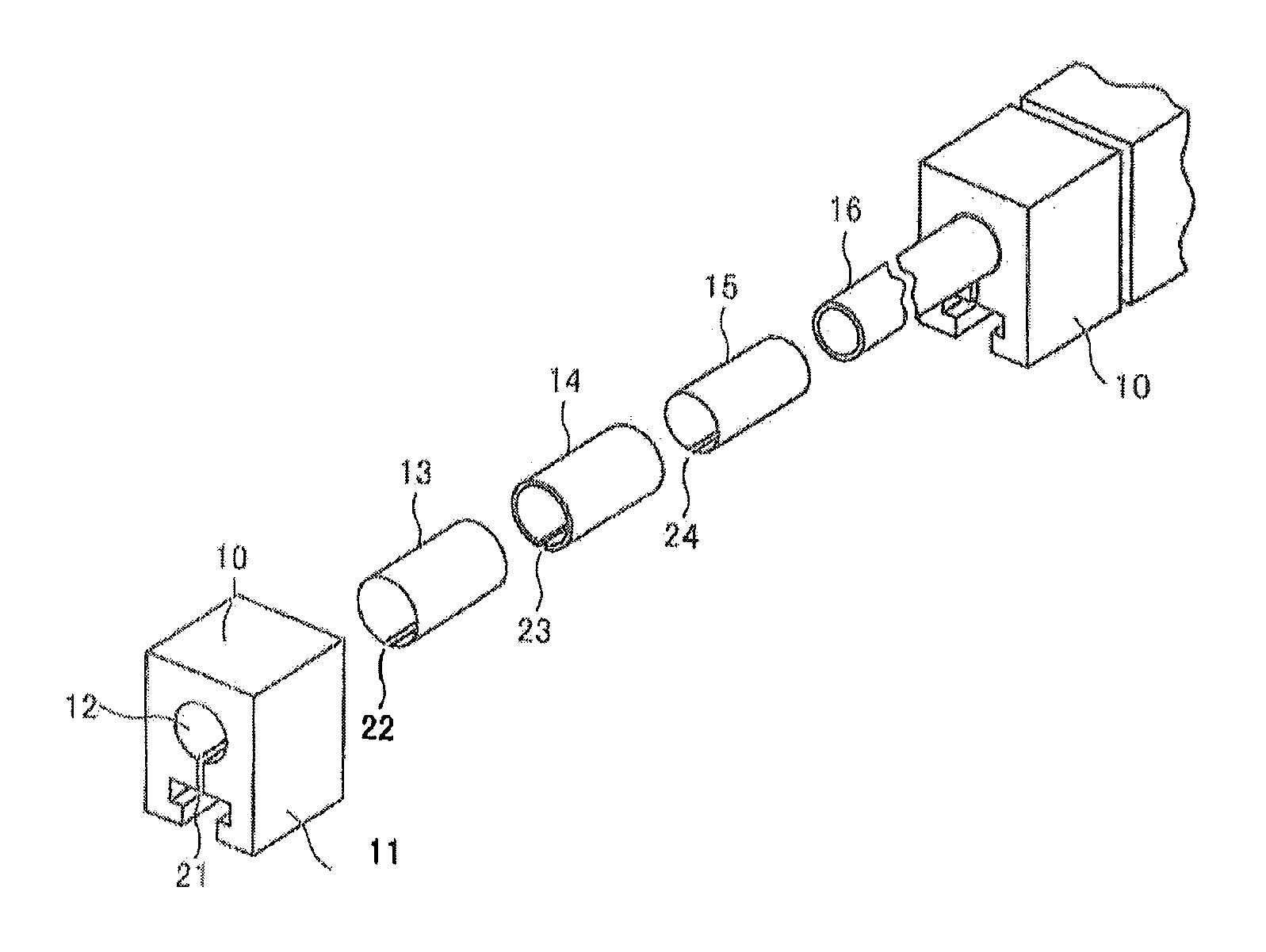
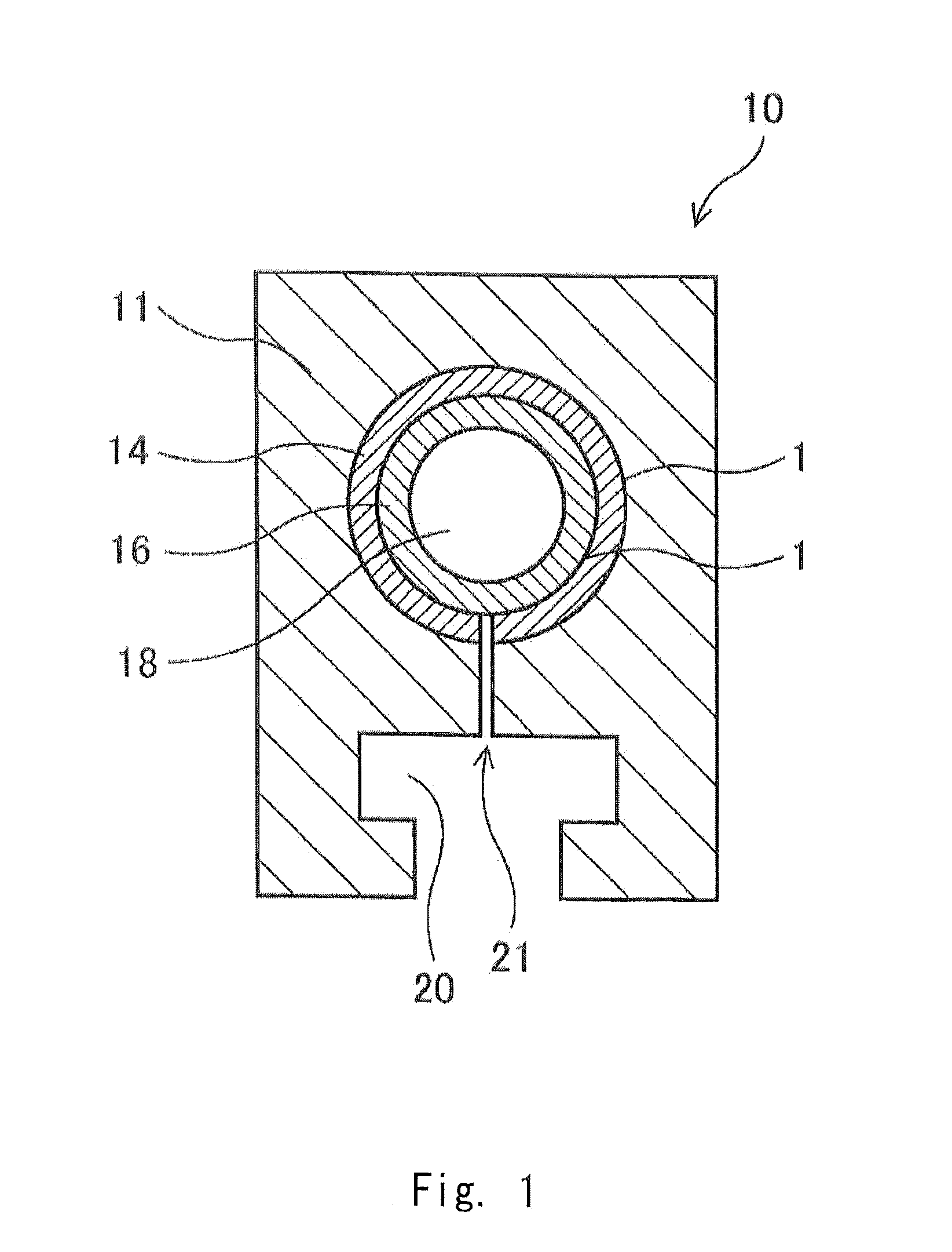
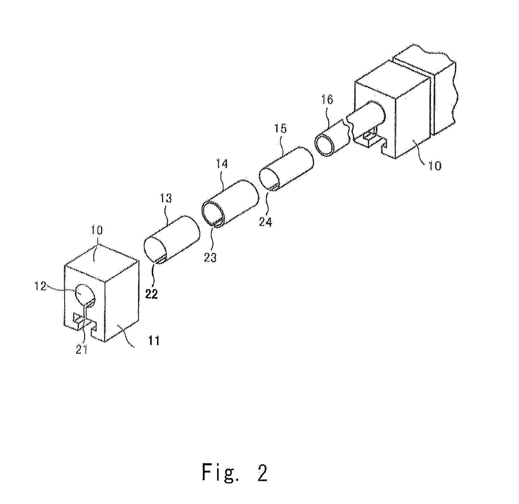
[0039]Hereinafter, high heat flux component, particularly a heat receiving tile used for a divertor of a nuclear fusion reactor and a manufacturing method thereof according to the present invention will be described in detail with respect to an embodiment. The present embodiment relates to a heat receiving tile used for the divertor of the Tokamak type nuclear fusion reactor. However, it is obvious that this invention can be widely applied to not only the plasma facing part of the blanket and the limiter of a nuclear fusion reactor but also a heat receiving tile formed by metallurgically joining a heat receiving block formed of a carbon material with a cooling tube formed of a copper alloy.

[0040]As shown in FIG. 1, the heat receiving tile 10 of this embodiment is provided with the heat receiving block 11 having a mono-block structure and formed of a carbon fiber reinforced composite material (CFC) and the cooling tube 16 formed of a copper alloy, such as chromium-zirconium copper (C...


PUM

PropertyMeasurementUnit
Thicknessaaaaaaaaaa
Efficiencyaaaaaaaaaa
Heataaaaaaaaaa

Abstract

A heat receiving block formed of carbon material having a through hole; a cooling tube formed of copper alloy fitted in the through hole of the heat receiving block; cylindrical material of interlayer disposed between the heat receiving block and the cooling tube; and brazing material layers inserted between the material of interlayer and the heat receiving block and between the material of interlayer and the cooling tube, also a slit which penetrates the heat receiving block and the material of interlayer over thickness of the heat receiving block and reaches the cooling tube on the back side of the heat receiving surface. It can provide heat receiving tile formed of carbon fiber composite material for high heat flux component such as a first wall of nuclear fusion reactor, which is produced by metallurgically joining carbon material with copper alloy and has higher cooling efficiency than conventional heat receiving tiles.

Description

TECHNICAL FIELD[0001]The present invention relates to a heat receiving tile formed of a carbon fiber composite material used heat receiving equipment for high heat flux panel such as a first wall of a nuclear fusion reactor which faces high temperature plasma or the like, and a method of manufacturing the same.BACKGROUND ART[0002]A plasma facing component provided in a nuclear fusion reactor refers in general to equipment directly opposed to plasma, includes a divertor, a blanket surface, a limiter or the like, and receives severe heat and particle load from high temperature plasma. The first wall is required to maintain structural integrity and serve as a shield against plasma for the surrounding structure without causing negative effects to the plasma.[0003]Therefore, the plasma facing component is required to have a function to well endure such a high heat load and remove the heat. In order to achieve the function of the first wall required for removing the heat of the high heat ...

Claims


Application Information

Patent Timeline
IPC IPC(8): F28D20/00B23K1/19C21D1/18C22F1/18C22F1/08B23K1/00B23K35/24
CPCF28D20/0056B23K1/0008B23K1/19B23K35/24B23K2203/16C22F1/08C21D1/18B23K2203/12B23K2203/14C22F1/183B23K35/0222B23K35/0238B23K35/0244B23K35/025B23K35/0255B23K35/30B23K35/302B23K2103/12B23K2103/14B23K2103/16G21B1/13Y02E30/10Y02E60/14
Inventor YAMADA, HIROKAZUMORI, YUUICHIROUSATOU, KOUJIMATSUNAMI, KIYOTAKAMAEDA, YASUTAKANAKAE, TAMOTSUKUBOTA, MAKOTOSAKURAI, SHINJINAKAMURA, SHIGETOSHIOZAKI, HIDETSUGU
Owner ATOX
Learn More