Apparatus for charging or adjusting the charge of aerosol particles

a technology for aerosol particles and charging devices, applied in the direction of instruments, particle separator tubes, corona discharge, etc., to achieve the effect of increasing the stability and performance of the device, and substantially reducing the formation of deposits on the corona discharge electrod

Inactive Publication Date: 2016-05-05
PARTICLE MEASURING SYST
View PDF5 Cites 15 Cited by
  • Summary
  • Abstract
  • Description
  • Claims
  • Application Information

AI Technical Summary

Benefits of technology

[0033]An object of the present invention is to create a particle charging device whereby gas ions are produced in an aerosol-free region by means of electrical discharge and are then moved into a separate zone where aerosol particles are introduced and

Problems solved by technology

All heavy industries involving processes emitting fumes have potential problems with the emission of aerosol particles.
There is also concern amongst consumer companies that use enzymes in washing powders, powder coatings and fibres used in disposable nappies and other products could cause problems.
In addition, the US EPA is becoming increasingly concerned about gasoline engine emissions.
Nano-particles and nano-objects are known to produce toxic effects.
Early studies with PTFE (polytetrafluoroethylene) particles around 20 nm in diameter showed that airborne concentrations of a supposedly inert insoluble material lower than 50 μg/m3 could be fatal to rats.
Real particles in the air often have complicated shapes.
The differences in shape and density cause considerable confusion in defining particle size.
However, it is not a true geometric size because non-spherical particles usually have a lower terminal settling velocity than spherical particles.
The investigation and monitoring of aerosol particles in the atmosphere has been hampered by a shortage of instruments which can take measurements over a wide particle size range but which are sufficiently inexpensive, robust and convenient to be used on a widespread basis.
The use of radioactive sources is limited by several disadvantages:The safety requirements concerning the radioactive source are high.The costs of purchase and maintenance are very high.The charging efficiency for small particles (dpLarger particles (dp>100 nm) are subject to multiple charging when a particle can carry more than 1 elementary electric charge.It is very difficult or impossible to increase charging efficiency or decrease multiple charging in devices built on the radioactive charging principle.
However, several problems need to be overcome in order to provide a corona-based device which is capable of replacing radioactive charging devices.
These problems include:ozone generation at higher voltage needed to generate corona discharge;ensuring stability of the corona discharge;contamination of the surface of the corona emitting electrode with chemical compounds formed by chemical reactions of air constituents with i

Method used


Image

  • Apparatus for charging or adjusting the charge of aerosol particles
  • Apparatus for charging or adjusting the charge of aerosol particles
  • Apparatus for charging or adjusting the charge of aerosol particles

Examples


example 1

[0124]An apparatus was built according to the embodiment shown in FIG. 5. All metal parts were made from stainless steel. The non-conductive parts were made of PTFE and a gold electrode of 0.2 mm diameter was used. The internal diameter of the ion generating chamber (item 1 in FIG. 5) was 16 mm. The opening 10 in the second electrode 9 was 2.5 mm in diameter and the thickness of the second electrode 9 was 1.5 mm. The mesh 17 was formed from stainless steel and the openings in the mesh were 120 μm (measured as the diagonal dimension of the opening).

example 2

[0125]Another example of an apparatus according to the invention was built according to the embodiment shown in FIG. 4. All metal parts were made from stainless steel. The non-conductive parts were made of PTFE and a gold electrode of diameter 0.1 mm was used. The internal diameter of the ion generating chamber 1 was 14 mm. The opening in the second electrode 9 was 2.5 mm in diameter and the thickness of the second electrode 9 was 1.5 mm.

example 3

[0126]A further example of an apparatus according to the invention was built according to the embodiment shown in FIG. 5. All metal parts were made from stainless steel, the non-conductive parts were made of PTFE and the electrode was made from Au of diameter 0.2 mm. The internal diameter of ion generating chamber 1 was 12 mm. The opening in the second electrode 9 was 3.5 mm and the thickness of the second electrode 9 was 1.5 mm. The mesh was formed from stainless steel and had 120 μm opening (measured as the diagonal of the openings). The aerosol flow rate was 0.2 l / min.

Test Results

[0127]Examples of apparatuses of the invention were tested using Zn, sebacate, ZnO, soot atmospheric aerosols and Cr2O3 aerosols. In each case, the ion concentration was measured with an ion counter and the aerosol particle size distributions were obtained with an NPS500 instrument (Naneum).

[0128]An illustration of the long-term stability of the charging corona (measured using the apparatus of Example 2)...


PUM


Abstract

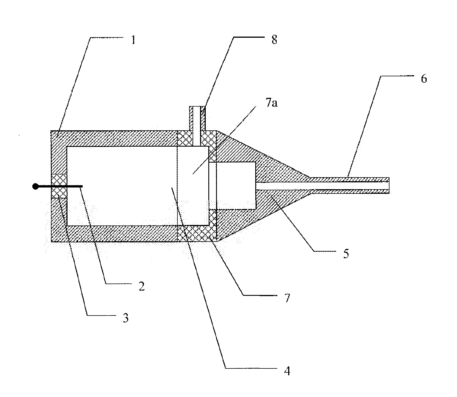
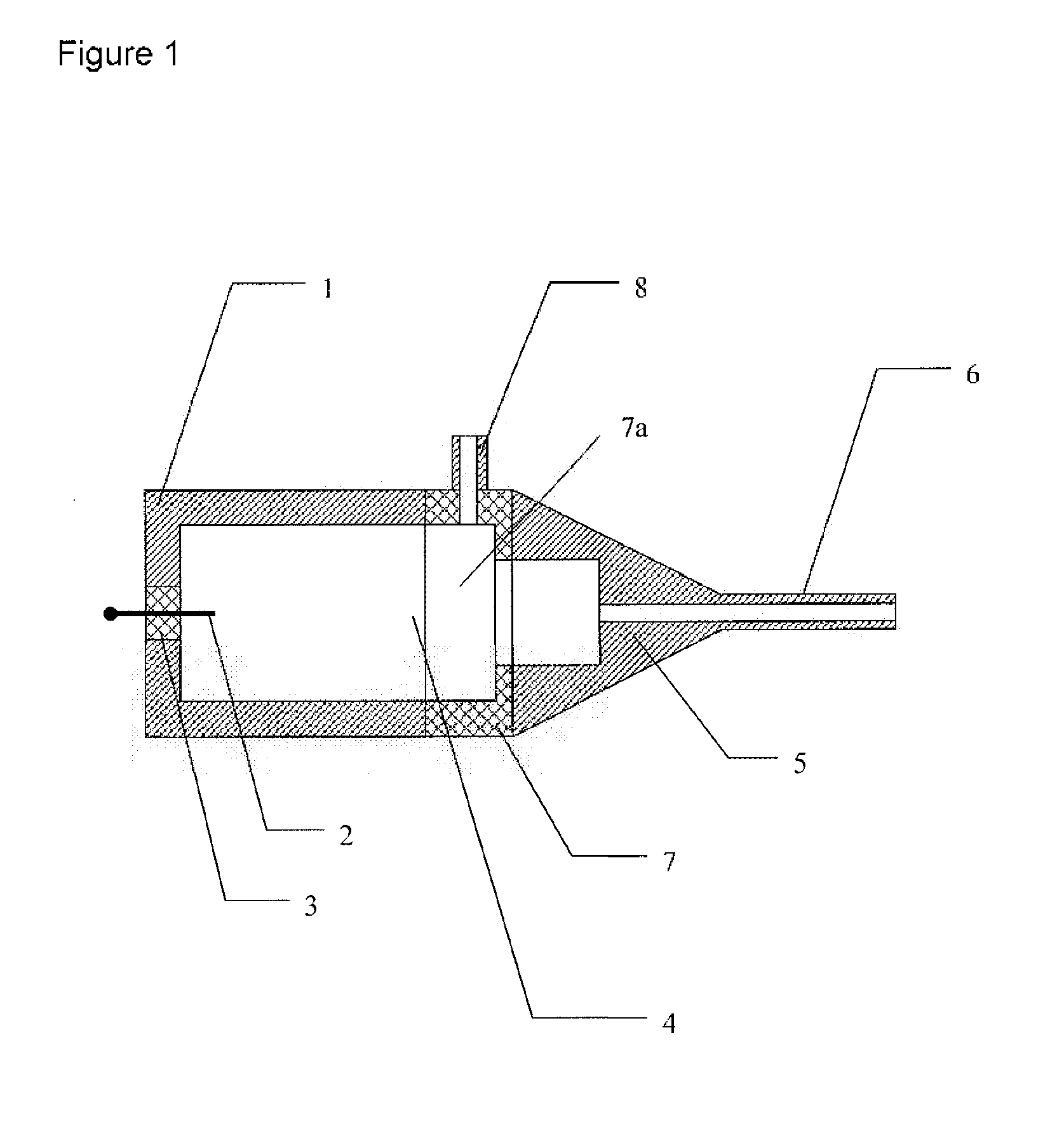
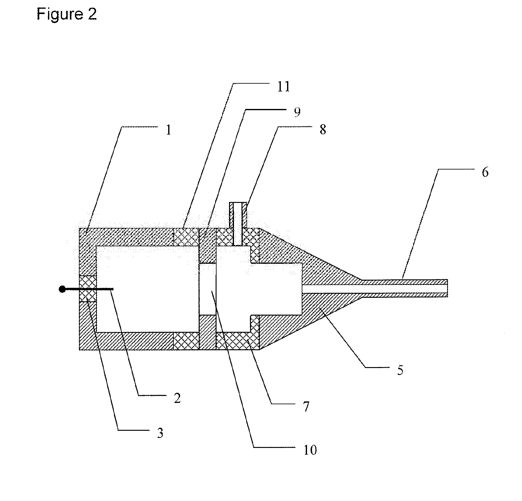
The invention provides an apparatus for charging or altering the charge of gas-entrained particles in an aerosol, the apparatus comprising:
(a) an ion generating chamber (1) containing a first electrode (2) for generating a corona discharge, the first electrode (2) being connected to a power supply of sufficiently high voltage to create the corona discharge; the ion generating chamber (1) having an ion outlet (10) through which ions generated by the corona discharge can leave the chamber (1);
(b) a particle charging chamber (5) in which charging or altering the charge of gas-entrained particles in an aerosol takes place, the particle charging chamber (5) being in fluid communication with the ion generation chamber (1) and having an inlet and an aerosol outlet; and
(c) an electrically non-conductive interface body (7) positioned between the aerosol particle charging chamber (5) and the ion generating chamber (1), the interface body (7) having a hollow interior which is in fluid communication with the ion generating chamber (1) and the aerosol particle charging chamber, and having a gas inlet (8) through which a stream of gas can be introduced into the hollow interior of the interface body (7).

Description

[0001]The invention relates to an apparatus for charging or adjusting the charge of aerosol particles by using corona discharge. More particularly, the invention relates to an apparatus where an ion generating region and a particle charging zone of the apparatus are spatially separated to reduce multiple charging and achieve greater long term charging stability.BACKGROUND OF THE INVENTION[0002]There is currently a great deal of concern about the health effects of nano-particles and micro-particles emitted unintentionally into the air. For example, a considerable increase in respiratory illness and allergies in the UK in recent years has been associated in part with particles emitted by diesel engines and other combustion processes. Whilst the main focus has been on diesel emissions, attention is turning to other potential sources such as power generation using fossil fuels, incineration, nuclear power generation and aircraft emissions. All heavy industries involving processes emitti...

Claims


Application Information

Patent Timeline
IPC IPC(8): H01J49/16H01J27/26
CPCH01J27/26H01J49/168H01J49/145
Inventor GORBUNOV, BORIS ZACHAR
Owner PARTICLE MEASURING SYST
Why Eureka
Try Eureka