
Belt-driven continuously variable transmission

a continuously variable transmission and belt drive technology, applied in the direction of gearing control, gearing elements, gearing, etc., can solve the problems of torque sensor not being able to establish a thrust force for moving the movable sheave, belt slippage, bearing damage, etc., to reduce power loss, limit damage, and save fuel

Active Publication Date: 2016-05-12
TOYOTA JIDOSHA KK
View PDF35 Cites 10 Cited by
  • Summary
  • Abstract
  • Description
  • Claims
  • Application Information

AI Technical Summary

Benefits of technology

The present invention aims to prevent damage on a continuously variable transmission (CVT) with a hydraulic chamber and torque cam assembly. The invention is achieved by actuating a piston to increase pressure in the hydraulic chamber, which ensures a required belt clamping pressure and prevents belt slippage. The torque cam assembly generates a thrust force based on the transmission torque, ensuring a quick response to prevent belt slippage. The oil pressure in the hydraulic chamber can be maintained at a low level without requiring a complex control, limiting damage on the output gear. The speed ratio of the CVT can be fixed, reducing power loss and fuel waste. The pressure in the hydraulic chamber can be increased even when there is no oil delivery, limiting damage on the belt-driven continuously variable transmission.

Problems solved by technology

That is, if the belt clamping pressure of the pulley is insufficient, a belt slip is caused on a contact face of the pulley.
For this reason, the bearing may be damaged by a thrust load.
However, according to the teachings of Japanese Patent Laid-Opens Nos. 2009-192018 and 11-72151, an actuating device for moving the piston toward the back side of the movable sheave is not available in the transmission.
Likewise, according to the teachings of No. 5-203006, the torque sensor is not adapted to establish a thrust force for moving the movable sheave.
According to the teachings of those prior art documents, therefore, belt slippage may be caused when hydraulic pressure applied to the hydraulic chamber is lowered by a trouble.

Method used


Image

  • Belt-driven continuously variable transmission
  • Belt-driven continuously variable transmission
  • Belt-driven continuously variable transmission

Examples


Embodiment Construction

)

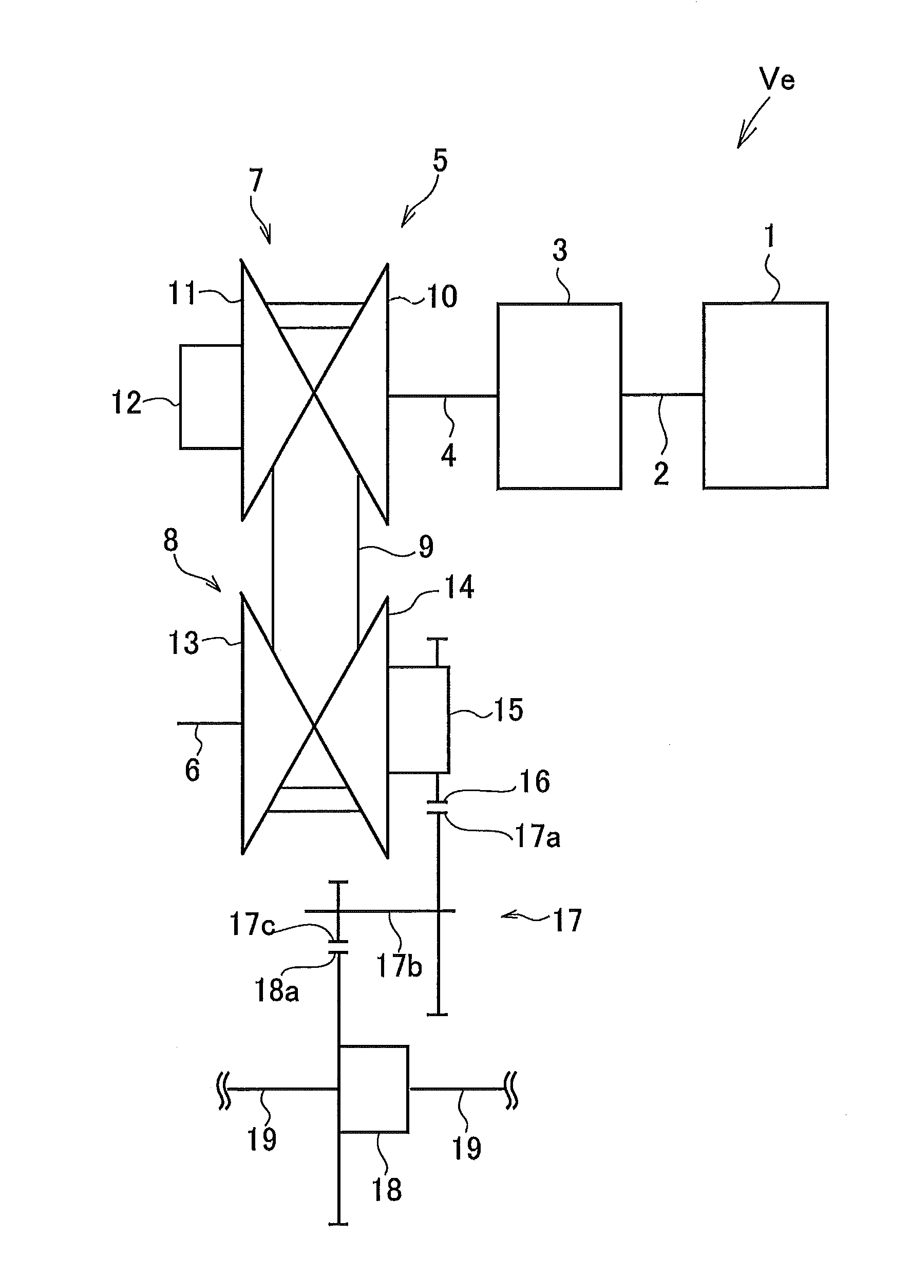
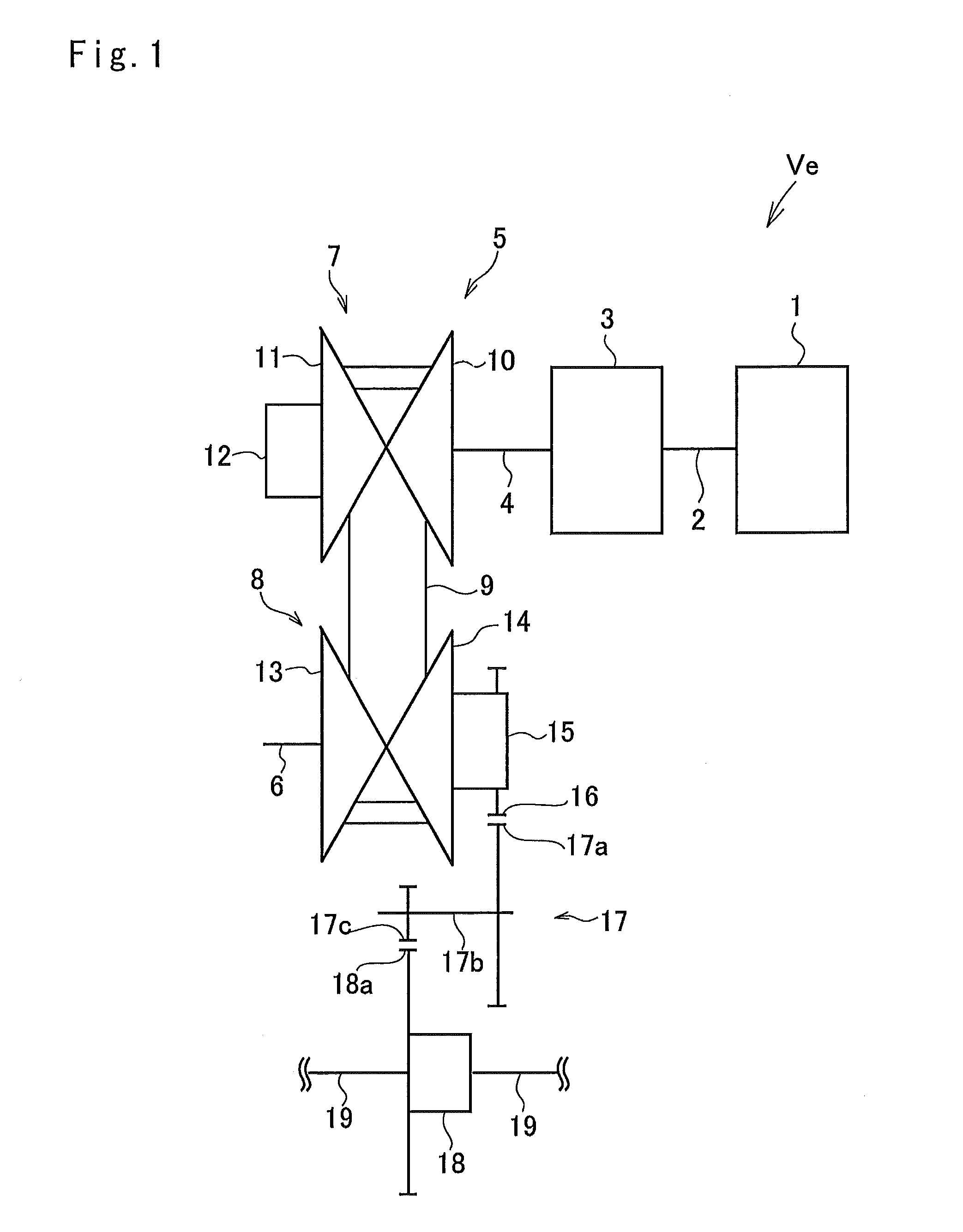
[0022]A preferred example of the present invention will be explained hereinafter. Referring now to FIG. 1, there is shown a powertrain of a vehicle to which a belt-driven continuously variable transmission according to the preferred example is applied. An engine 1 show in in FIG. 1 serving as a prime mover of a vehicle Ve includes a gasoline engine and a diesel engine, and an output torque of the engine 1 is controlled by operating an accelerator.

[0023]A crank shaft 2 of the engine 1 is connected to a transmission device 3 such as a torque converter or a torque reversing device. The transmission device 3 is connected to a belt-driven continuously variable transmission 5 through a drive shaft 4 so that an output torque of the engine 1 is delivered to the belt-driven continuously variable transmission 5 via the crank shaft 2, the transmission device 3 and the drive shaft 4.

[0024]The belt-driven continuously variable transmission (hereinafter abbreviated as the “CVT”) 5 comprises a dr...


PUM


Abstract

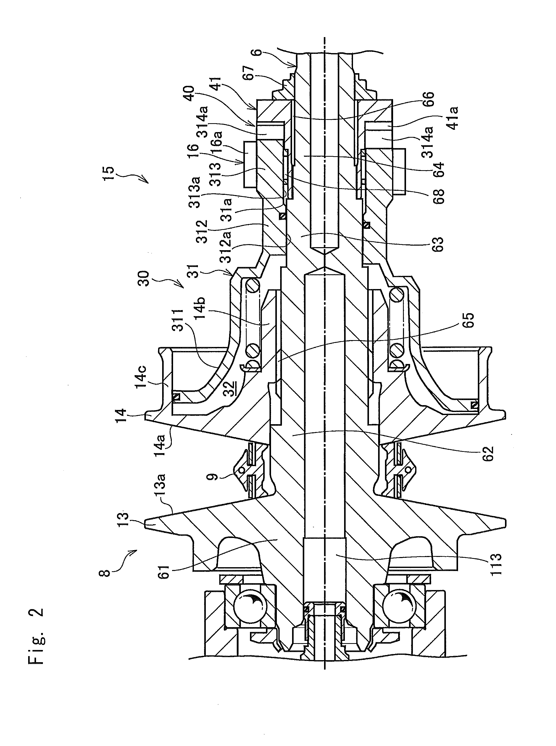
A belt-driven continuously variable transmission adapted to prevent an occurrence of belt slippage is provided. The continuously variable transmission comprises a hydraulic actuator formed on a back side of a movable sheave to change a belt groove between a fixed sheave and a movable sheave, and a torque cam assembly adapted to convert a torque into an axial thrust force by a relative rotation between a pair of cam members contacted to each other. In the belt-driven continuously variable transmission, a piston fitted onto a shaft of the driven pulley while allowing to rotate relatively therewith and to reciprocate thereon is integrated with one of the cam members of driven side and with an output gear for outputting torque of the pulley. The cam member of drive side is fixed in an axial direction on a driven shaft to be rotated integrally therewith.

Description

TECHNICAL FIELD[0001]This invention relates to a belt-driven continuously variable transmission adapted to change a speed ratio continuously by varying an effective diameter position of a driving belt running between pulleys.BACKGROUND ART[0002]A conventional belt-driven continuously variable transmission comprises a pair of pulleys, an endless driving belt running between the pulleys, and a hydraulic chamber formed on each pulley. Oil is delivered to the hydraulic chamber of a drive pulley to change a speed ratio, and oil is delivered to the hydraulic chamber of a driven pulley to establish a belt clamping pressure. In the belt-driven continuously variable transmission thus structured, therefore, a speed ratio can be varied continuously by hydraulically changing groove widths of the pulleys to change running diameter positions of the belt.[0003]However, in the belt-driven continuously variable transmission, power transmission is achieved frictionally between the belt and each pulle...

Claims


Application Information

Patent Timeline
Patent Type & Authority Applications(United States)
IPC IPC(8): F16H9/18
CPCF16H9/18F16H61/66272F16H55/56
Inventor KAWAKAMI, TAKAHOYANAGIDA, TOMOAKI
Owner TOYOTA JIDOSHA KK
Learn More