
Method and device for producing a photovoltaic element with stabilised efficiency

a photovoltaic element and efficiency stabilisation technology, applied in the field of photovoltaic element production, can solve the problems of significant efficiency loss of more than 1% abs, bottleneck in production, and reduce the efficiency of solar cells over time, so as to achieve stable efficiency, short process time, and the effect of producing a photovoltaic element with stabilised efficiency

Active Publication Date: 2016-05-19
UNIV KONSTANZ
View PDF4 Cites 13 Cited by
  • Summary
  • Abstract
  • Description
  • Claims
  • Application Information

AI Technical Summary

Benefits of technology

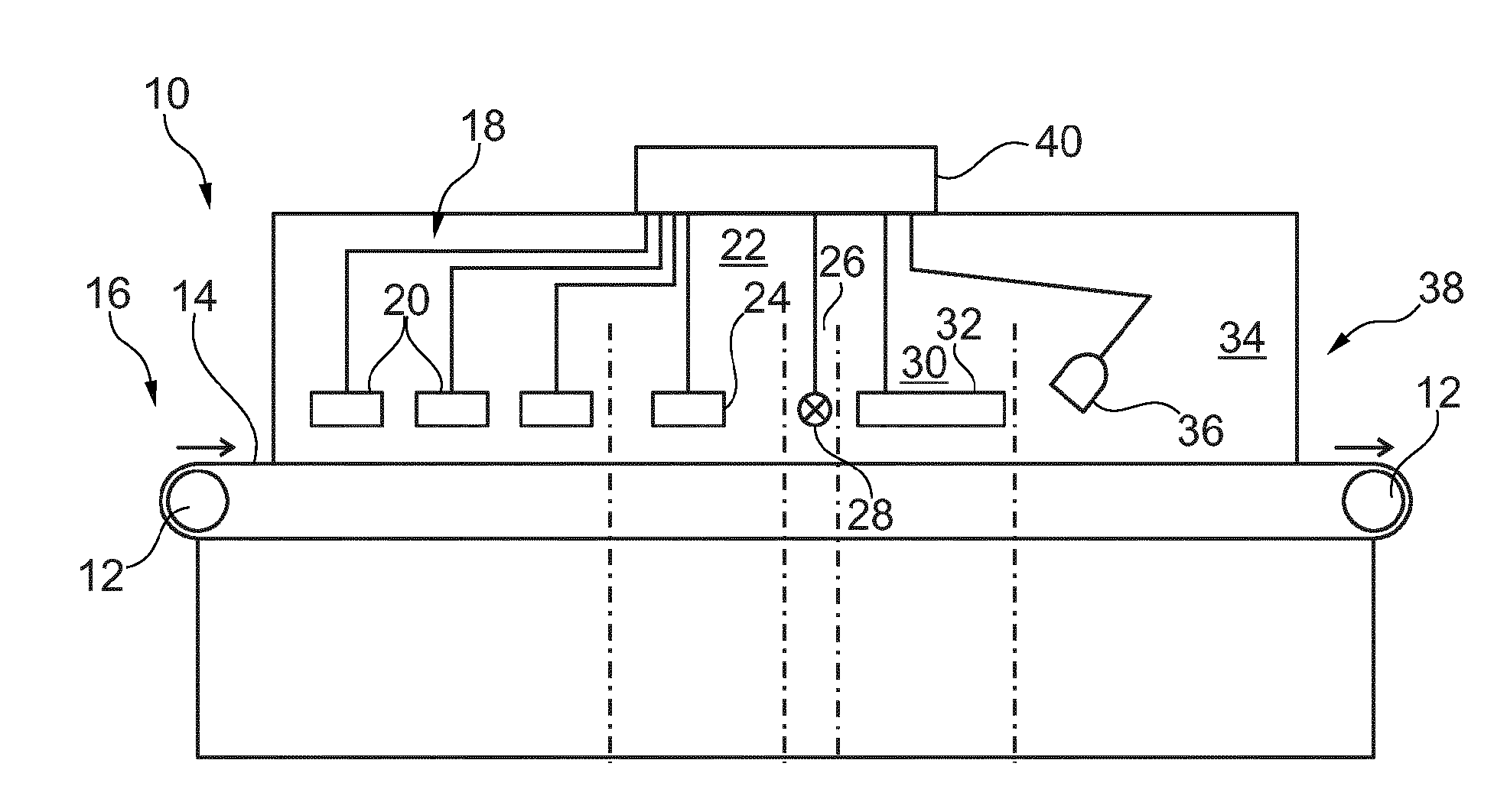
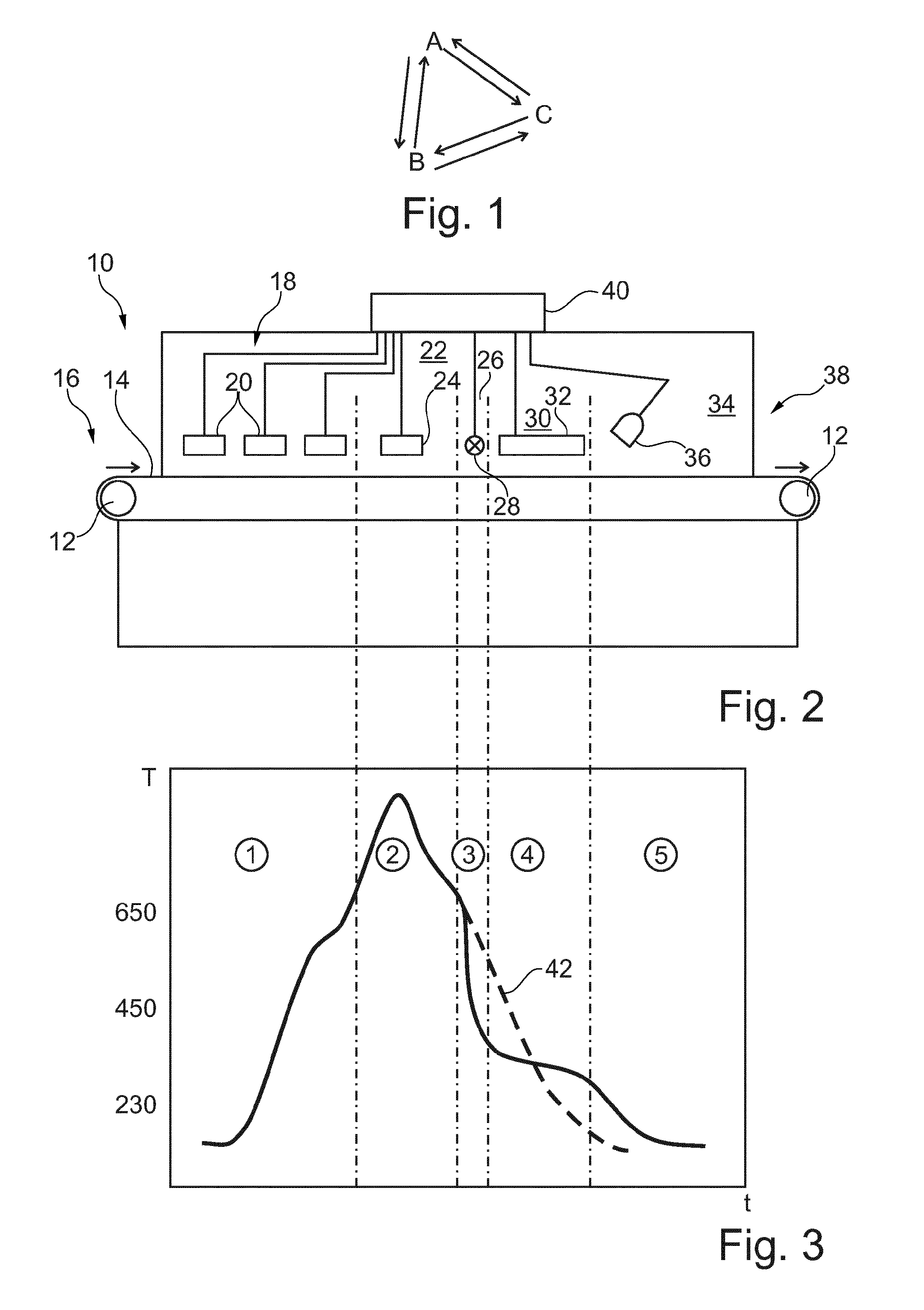
The patent text describes a method for producing a photovoltaic element with stabilized efficiency. By adding additional process steps or choosing suitable process parameters, the rate of regeneration during the stabilization treatment step can be increased, and the period of time required for stabilization can be shortened. This allows for a more efficient production process. Additionally, the text describes a method for simultaneously carrying out contact formation and regeneration of the silicon substrate, which can further shorten the stabilization treatment step. The method also involves depositing a hydrogen-containing dielectric layer or a double antireflection coating on the surface of the silicon substrate, which can serve as an antireflection layer, a passivating layer, or a dielectric mirror for the solar cell. The method also suggests maintaining the silicon substrate at a temperature range of from 230°C to 450°C to generate excess minority charge carriers, which can further shorten the duration of the stabilization treatment step.

Problems solved by technology

It has been observed many times that, in the case of solar cells produced on the basis of crystalline silicon wafers, degradation effects may occur which reduce the efficiency of the solar cell over time.
Significant efficiency losses of up to more than 1% abs have been observed.
In the case of an automated industrial manufacturing line in particular, this may lead to delays and thus to the formation of a bottleneck in production.

Method used


Image

  • Method and device for producing a photovoltaic element with stabilised efficiency
  • Method and device for producing a photovoltaic element with stabilised efficiency

Examples


Embodiment Construction

[0044]Embodiments of the invention described hereinbelow relate in the broadest sense to a method for passivating or rendering harmless electrically active defects in silicon-based photovoltaic elements such as, for example, solar cells and solar modules. In particular, the defects may be boron-oxygen correlated defects, as are described in the literature, which may reduce considerably a quality (described by the (statistical) lifetime of the minority charge carriers) of the starting material and electrical performance parameters, which are dependent thereon, of the solar cell (current, voltage, efficiency under illumination) especially of monocrystalline but also generally of multicrystalline silicon or solar cells. An action of the method proposed herein on other defects too may not be ruled out.

[0045]A solar cell or a solar module is used to convert energy of incident ultraviolet / visible / infra-red light directly into electrically usable energy without using heat as an intermediat...


PUM


Abstract

According to an example, in a method for producing a photovoltaic element with stabilised efficiency, a silicon substrate may be provided with an emitter layer and electrical contacts, which may be subjected to a stabilisation treatment step. Hydrogen from a hydrogenated silicon nitride layer may be introduced into the silicon substrate, for example, within a zone of maximum temperature. The silicon substrate may then be cooled rapidly in a zone in order to avoid hydrogen effusion. The silicon substrate may then be maintained, for example in a zone within a temperature range of from 230° C. to 450° C. for a period of, for example, at least 10 seconds. The previously introduced hydrogen may thereby assume an advantageous bond state. At the same time or subsequently, a regeneration may be carried out by generating excess minority charge carriers in the substrate at a temperature of at least 90° C., preferably at least 230° C.

Description

FIELD OF THE INVENTION[0001]The present invention relates to a method for producing a photovoltaic element whose efficiency is stabilised by a stabilisation treatment step. In particular, the present invention relates to a method for producing a solar cell based on a boron-doped, oxygen-containing silicon substrate. The invention relates further to a device for treating a silicon substrate within the context of the production of a photovoltaic element, wherein the device is configured to carry out the stabilisation treatment step of the method according to the invention.TECHNICAL BACKGROUND[0002]Solar cells, as photovoltaic elements, serve to convert light into electric current. Light-generated charge carrier pairs, which have been spatially separated, for example, at a pn junction between an emitter region and a base region, must thereby be fed to an external current circuit by means of electrical contacts of the solar cell. Electrical contact arrangements must be provided for that...

Claims


Application Information

Patent Timeline
IPC IPC(8): H01L31/18H01L21/67F27B9/06H01L31/068
CPCH01L31/1864H01L31/068F27B9/066H01L21/67109H01L21/67115H01L31/1804H01L31/1868Y02E10/547H01L21/67248H01L21/6776F27B9/40Y02P70/50
Inventor HERGUTH, AXELWILKING, SVENJA
Owner UNIV KONSTANZ
Learn More