Flip cover plate for mobile terminal

a mobile terminal and flip cover technology, applied in the field of flip cover plates for mobile terminals, can solve the problems of increased manufacturing costs, low production efficiency, and high price of smart phones equipped with various functions, and achieve the effects of reducing manufacturing costs, simplifying molds, and maximizing productability

Active Publication Date: 2016-05-19
LEE NAM HEE +2
View PDF0 Cites 9 Cited by
  • Summary
  • Abstract
  • Description
  • Claims
  • Application Information

AI Technical Summary

Benefits of technology

[0027]Accordingly, the present invention may maximize productability as compared with conventional methods of manufacturing products by performing individual cutting processes using a NC machine.
[0028]Further, upon injection of the cover plate, the transparent window is not simultaneously formed, and thus, the molds may be simplified in shape, thus reducing manufacture costs. Further, production of parts proceeds in parallel, leading to further shortened production time along with a decreased defect rate.
[0029]Further, a reinforcing member is provided on a side of the transparent window, preventing a deformation of the cover plate or detachment of the transparent window due to a warp.
[0030]Further, according to another embodiment of the present invention, the transparent window may be form

Problems solved by technology

Among others, smartphones equipped with various functions are selling expensive, and accordingly, protective cases are gaining popularity to protect the phones.
As such, the manufacture of cover plate is done individually, i.e., unit-by-unit, resulting in low production efficiency and increased manufacture costs.
Further, such m

Method used


Image

  • Flip cover plate for mobile terminal
  • Flip cover plate for mobile terminal
  • Flip cover plate for mobile terminal

Examples


first embodiment

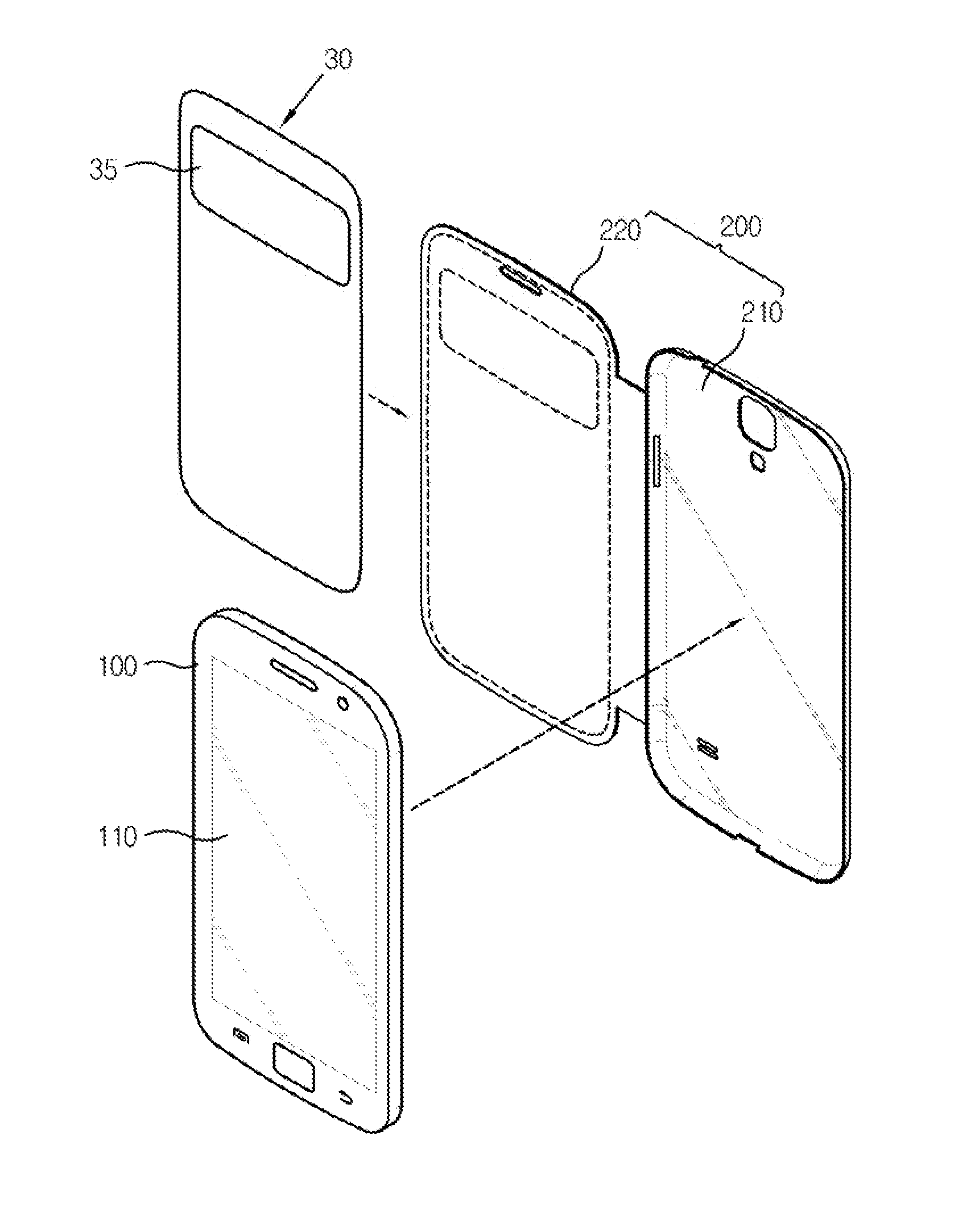
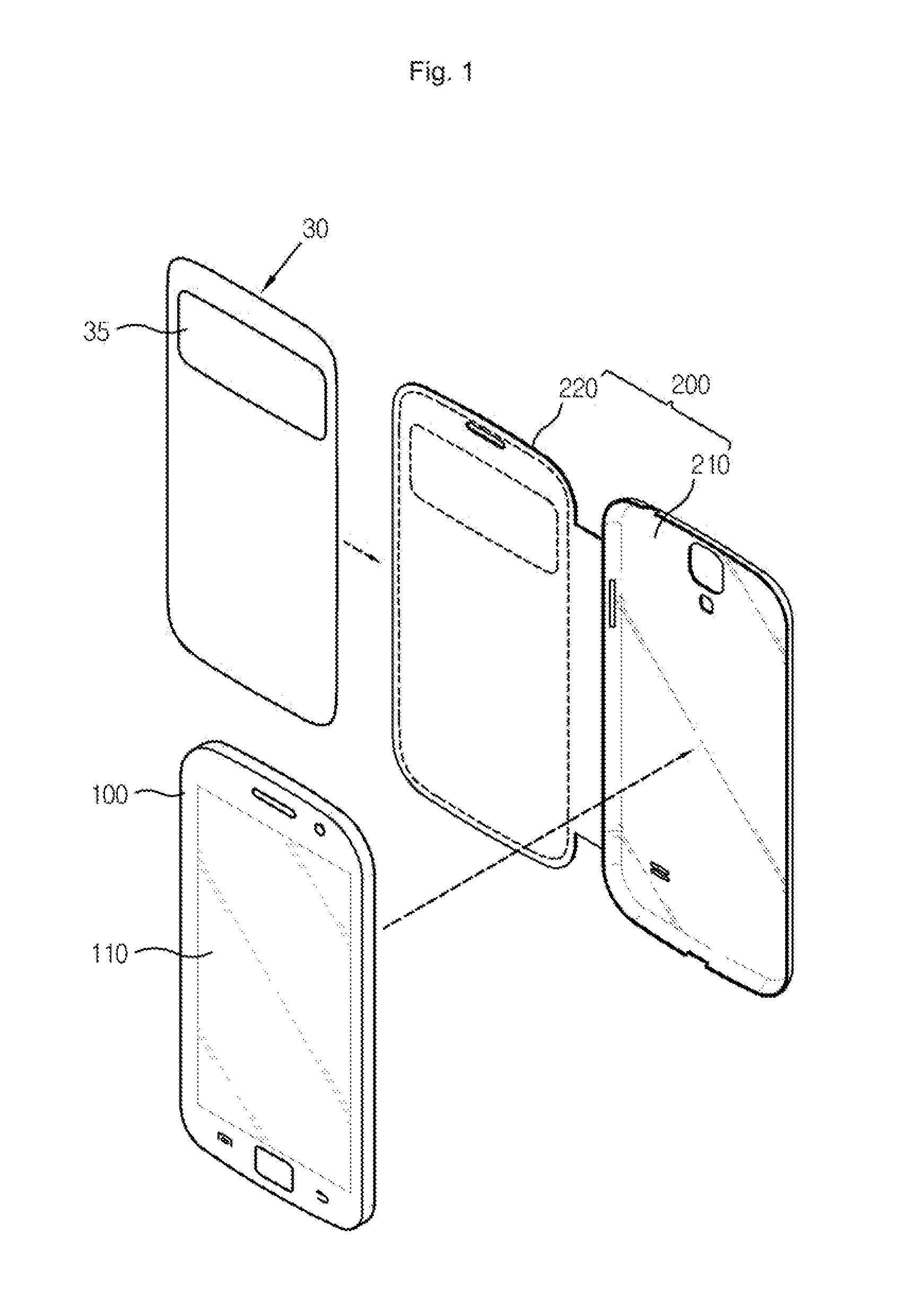
[0043]According to the first embodiment of the present invention, in the flip cover plate 10 for a mobile terminal, the transparent window 35 is formed by performing an injection molding process on a transparent material, and is then attached to the cover plate 30.

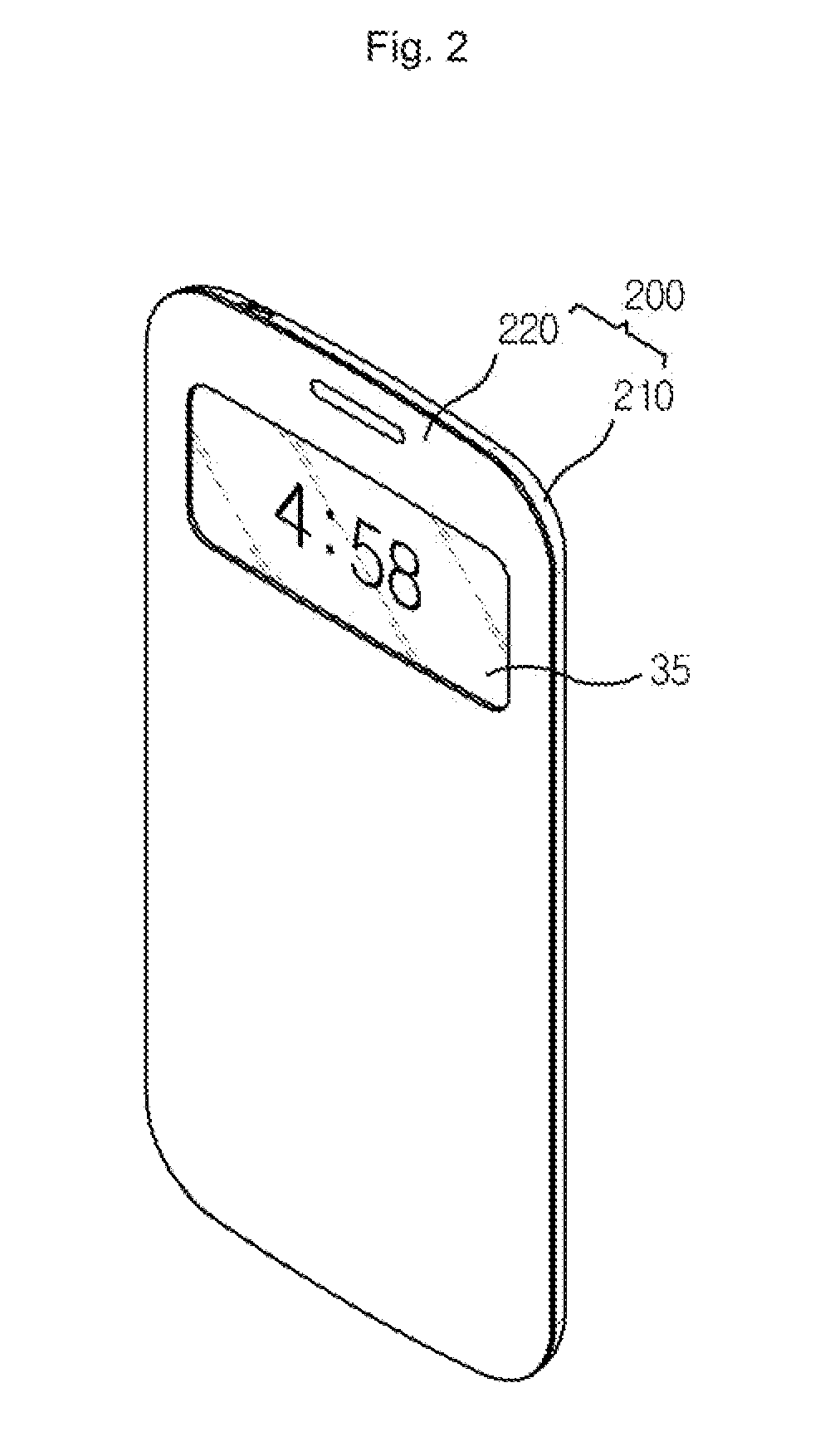
[0044]The cover plate 30 is placed in the flip cover 220 opening and dosing the front surface 110 of the mobile terminal 100, as shown in FIG. 1.

[0045]The flip cover 220 is rotatably coupled to the case body 210 coupled with the mobile terminal 100 at a rear surface and site surfaces thereof.

[0046]The cover plate 30 according to the present invention is preferably manufactured by an injection molding method as proposed in the Applicant's prior patent application, Korean Patent Application No. 2013-0060963.

[0047]Accordingly, as compared with conventional manufacturing methods using individual cutting through an NC machine, the present invention may maximize productability.

[0048]Further, unlike in the above-mentioned patent ...

second embodiment

[0068]According to the second embodiment of the present invention, in the flip cover plate 10 for a mobile terminal, the transparent window 35 is formed by stacking multiple films including a base film 355.

[0069]That is, according to this embodiment, the transparent window 35 may be provided with multiple film layers and may be attached onto the cover plate 30. For example, as shown in FIG. 4, the transparent window 35 may include the base film 355, an adhesive layer 356 formed on a side surface of the base film 355, facing the cover plate 30, a hardness reinforcing coating layer 357 formed on the other side surface of the base film 355, and a protective film 358 formed on the hardness reinforcing coating layer 357.

[0070]Here, the base film 355 may be formed of polyethylene terephthalate (PET), and the adhesive layer 356 may be formed of an optically clear adhesive (OCA).

third embodiment

[0071]According to the third embodiment of the present invention, in the flip cover plate 10 for a mobile terminal, the transparent window 35 is attached on to surface of the cover plate 30 by a hard coating film 359.

[0072]That is, according to this embodiment, a case 200 includes a case body 210 covering a rear surface and sick surfaces of the mobile terminal 100, a flip cover 220 rotatably provided on a side of the case body 210 to open and close the front surface 110 of the mobile terminal 100, and a cover plate 30 inserted in the flip cover 220.

[0073]The case body 210 is formed to have an opening at a surface thereof to provide a space for accommodating the mobile terminal 100, and the flip cover 220 is coupled to the case body 210 via a soft material to be rotatable. The flip cover 220 rotates about the case body 210 to open and close the front surface 110 of the mobile terminal 100 accommodated in the case body 210. That is, the flip cover 220 externally exposes or blocks and ...


PUM


Abstract

The present invention relates to a flip cover plate (10) for a mobile terminal, the plate comprising: a cover plate inserted into a flip cover which opens and closes the front portion of the mobile terminal; and a transparent window coupled to one side of the cover plate and exposing a portion of a liquid crystal of the mobile terminal to the outside when the flip cover is positioned at the front portion of the mobile terminal, wherein the transparent window is configured to be bonded to at least one surface of the cover plate corresponding to in opening of the flip cover. Accordingly, the present invention has an advantage of maximizing productivity compared to production through one by one cutting processes by means of a conventional numerically controlled machine tool. Furthermore, since the transparent window is not simultaneously molded when the cover plate is injection-molded, the present invention has advantages of simplifying the shape of a mold, thereby being capable of reducing manufacturing costs, as well as reducing manufacturing time and also the failure rate of products since the manufacturing of parts proceeds in parallel.

Description

TECHNICAL FIELD[0001]The present invention relates to a flip cover plate for a mobile terminal, in which an injection molding process, instead of conventional individual processing through a machine tool, is applied to a cover plate, and a transparent window is separately formed and attached to the cover plate, thus leading to reduced manufacture costs for flip cover plates, maximized productability, and increased product reliability.DISCUSSION OF RELATED ART[0002]As use of smartphones, such as the Galaxy™ or Iphone™, becomes more and more commonplace, various accessories for mobile phones are coming to market.[0003]Among others, smartphones equipped with various functions are selling expensive, and accordingly, protective cases are gaining popularity to protect the phones.[0004]Referring to FIG. 1, a protection case typically includes a case body 210 covering the rear and side surfaces of a mobile phone 100 thereof and a flip cover 220 rotatably coupled with the case body 210 at a ...

Claims


Application Information

Patent Timeline
IPC IPC(8): H04B1/3888H04M1/02
CPCH04B1/3888H04M1/0214H04M1/0202A45C11/00A45C2011/002A45C2200/05H04M1/185A45C13/002A45C2200/10
Inventor YUN, NAM WOONYUN, MIN SEOKLEE, NAM HEE
Owner LEE NAM HEE
Why Eureka
Try Eureka