Resonant System and Method of Determining a Dielectric Constant of a Sample

a dielectric constant and sample technology, applied in the field of detection of explosives, can solve the problems of difficult calibration with reference standards, resonator system, and inapplicability to loose powders or liquids, etc., and achieve the effect of reducing the size of the requisite cavity, reducing the wavelength of electromagnetic radiation, and minimizing the sample siz

Active Publication Date: 2016-05-26
BATTELLE MEMORIAL INST
View PDF5 Cites 9 Cited by
  • Summary
  • Abstract
  • Description
  • Claims
  • Application Information

AI Technical Summary

Benefits of technology

[0011]The present invention is also directed to a method of determining a dielectric constant comprising placing a sample in a fixture so that the sample is encased in the fixture and is part of a resonator in a resonant system. A harmonic electric field is applied to the sample, and the harmonic electric field reflected from or transmitted therethrough is measured. The dielectric constant of the sample is determined at harmonic frequencies of the electromagnetic radiation. Preferably, the sample is precisely placed within the fixture. The method also includes reducing a wavelength of the electromagnetic radiation with the fixture and setting a frequency at which the system measures the dielectric constant of the sample by changing the size...

Problems solved by technology

This type of configuration is not suited for loose powders or liquids or practical for all materials.
However, such an open resonator system has ma...

Method used


Image

  • Resonant System and Method of Determining a Dielectric Constant of a Sample
  • Resonant System and Method of Determining a Dielectric Constant of a Sample
  • Resonant System and Method of Determining a Dielectric Constant of a Sample

Examples


Embodiment Construction

[0028]Detailed embodiments of the present invention are disclosed herein. However, it is to be understood that the disclosed embodiments are merely exemplary of the invention that may be embodied in various and alternative forms. The figures are not necessarily to scale, and some features may be exaggerated or minimized to show details of particular components. Therefore, specific structural and functional details disclosed herein are not to be interpreted as limiting, but merely as a representative basis for teaching one skilled in the art to employ the present invention.

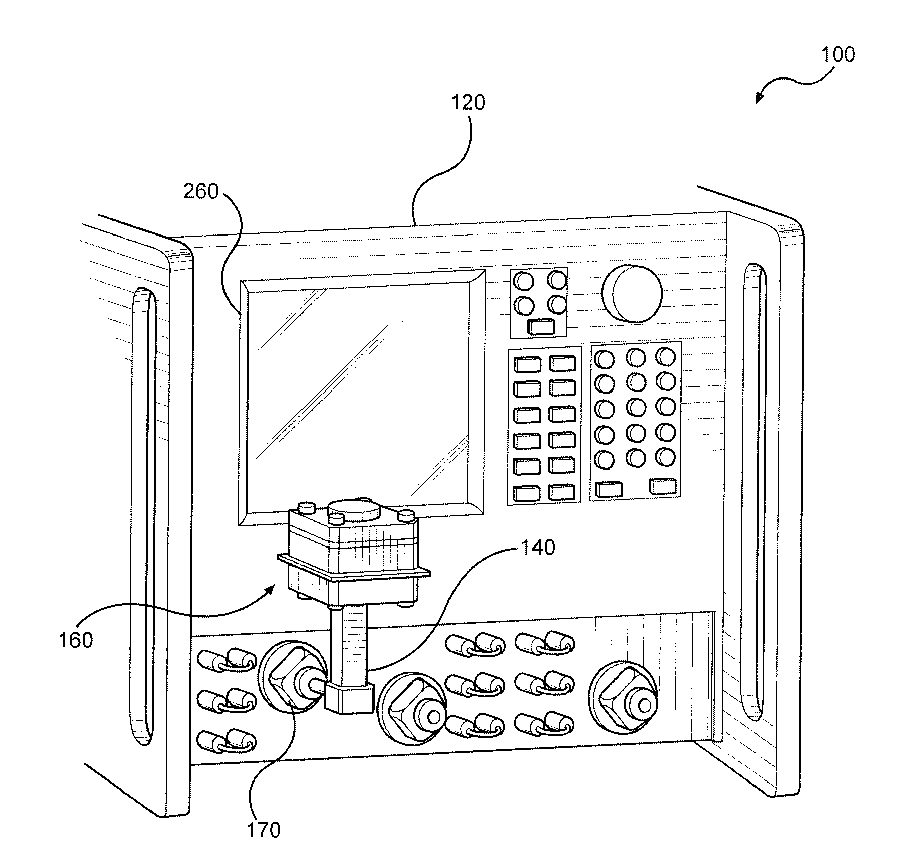
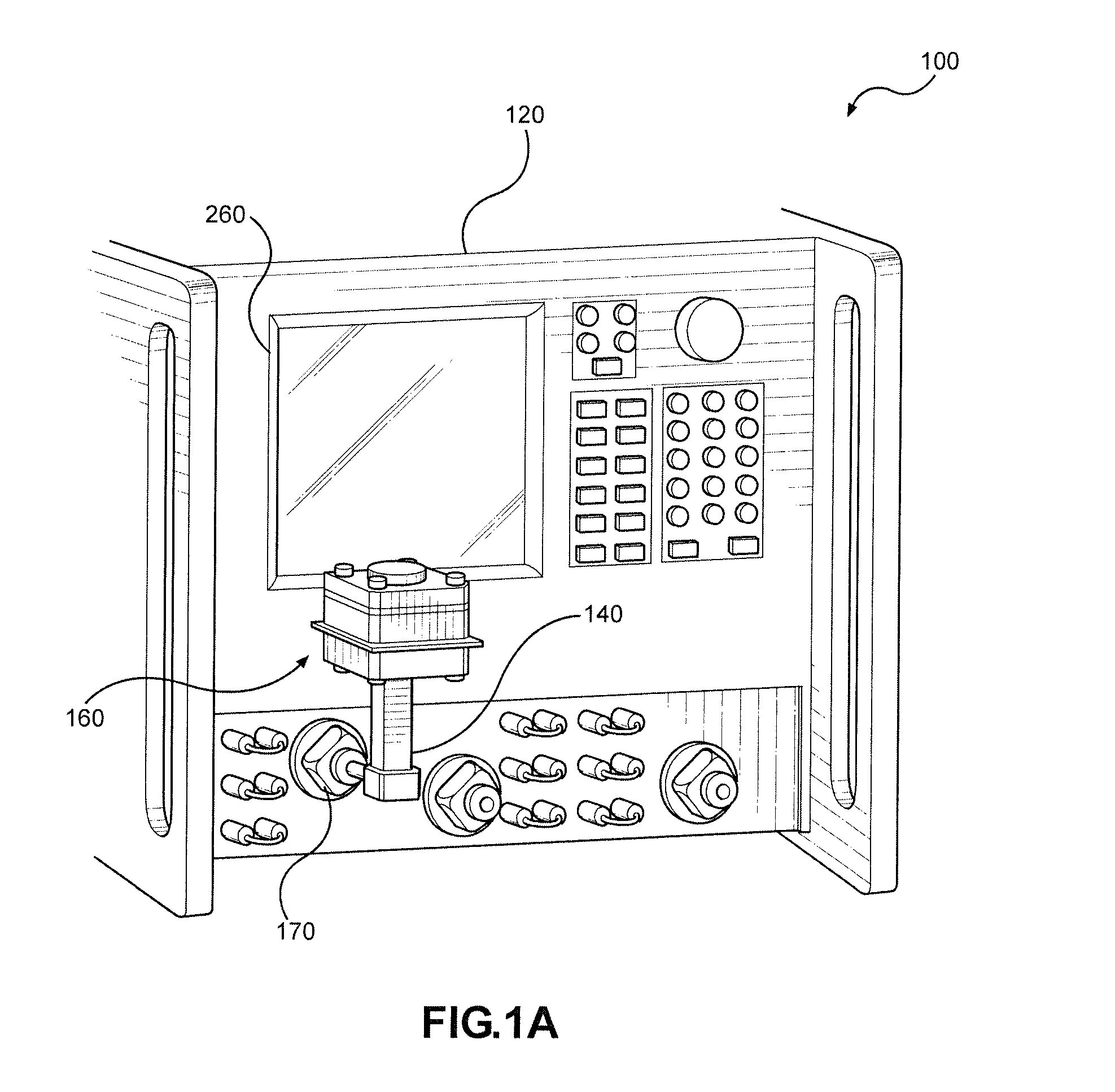
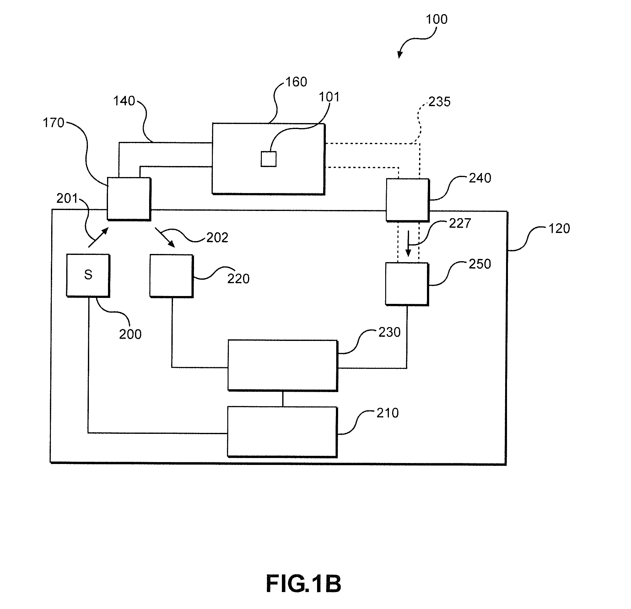
[0029]As depicted in FIGS. 1A-C, the present invention pertains to a resonant cavity based system 100 for measuring the dielectric constant of a sample 101 of material. System 100 has three main components: a network analyzer 120, a transmission waveguide 140 and a device 160 for holding sample 101. Preferably, transmission waveguide 140 is connected to network analyzer 120 at a port 170 and to device 160 and is ar...


PUM


Abstract

The present invention pertains to a resonant cavity system, more specifically, a resonant system for measuring the dielectric constant of a sample and its method of use. The system and method provide for holding sample materials, which can be in solid, liquid, or powder form, and for reducing the size of the requisite cavity for measurement. The construction incorporates waveguide flange connectors to seal the electromagnetic cavity, which facilitates the measurement of low-loss materials. The design for signal input enables the use of standard calibration techniques and measurement.

Description

CROSS REFERENCE TO RELATED APPLICATIONS[0001]This application claims the benefit of U.S. Provisional Patent Application Ser. No. 62 / 083,561, which was filed on Nov. 24, 2014 and titled “Fixtures for Solids, Liquids, and Powders for the Measurement of Electromagnetic Properties of Materials and the Miniaturization of a Resonant Cavity Measurement Apparatus”. The entire content of this application is incorporated by reference.STATEMENT REGARDING FEDERALLY SPONSORED RESEARCH OR DEVELOPMENT[0002]This invention was made with government support under Contract No. HSHQDC-12-F-00048 awarded by the Department of Homeland Security. The government has certain rights in the invention.BACKGROUND OF THE INVENTION[0003]There is a prevailing need for the detection of explosives, particularly in the aviation industry, but also in other mass transit modes of transportation. More specifically, there exists a need for technology to detect various explosives and hazardous materials that are in liquid or...

Claims


Application Information

Patent Timeline
IPC IPC(8): G01R27/26G01N22/00
CPCG01N22/00G01R27/2664
Inventor WEATHERALL, JAMES C.BARBER, JEFFREYSMITH, BARRY T.
Owner BATTELLE MEMORIAL INST
Why Eureka
Try Eureka