
Photocatalyst sheet

Active Publication Date: 2016-06-09
NITTO DENKO CORP
View PDF5 Cites 13 Cited by
  • Summary
  • Abstract
  • Description
  • Claims
  • Application Information

AI Technical Summary

Benefits of technology

The patent describes a photocatalyst sheet that has been deposited onto a surface using an aerosol deposition method, resulting in a strong and durable layer. This sheet exhibits excellent antifouling and other photocatalyst functions over extended time periods. Additionally, the patent discusses the option of using a binder resin to attach photocatalyst particles to the base material. However, this method decreases the photocatalytic activity and adhesion to the base material. The technical effects of this patent are improved photocatalytic activity and durability, as well as better adhesion to the base material.

Problems solved by technology

A drawback of the photocatalyst sheet of Patent Literature 2, however, is that the photocatalyst layer detaches itself and exfoliates from the nonwoven fabric because of the poor adhesion between the photocatalyst and the nonwoven fabric.
As a result, the photocatalyst sheet cannot properly exhibit the desired photocatalyst functions.

Method used

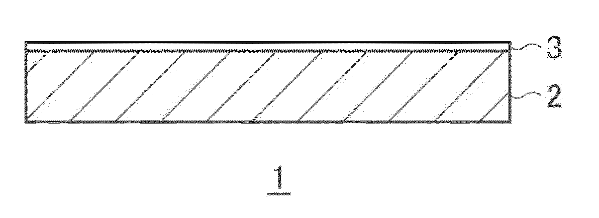
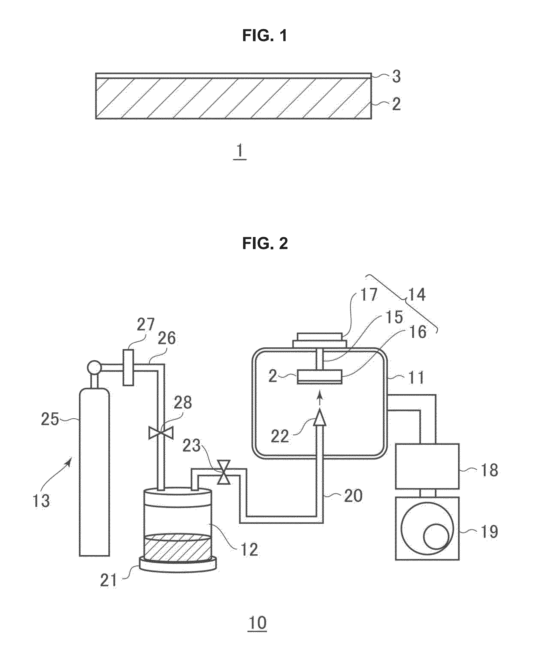
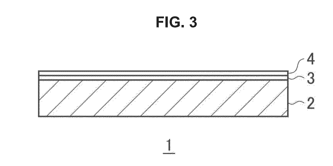

Image

  • Photocatalyst sheet
  • Photocatalyst sheet
  • Photocatalyst sheet

Examples


example 1

[0300]Firstly, a PET nonwoven fabric (Toyobo Co., Ltd.; thickness 150 μm; basis weight 20 g / m2) was prepared as the base material which is a porous film.

[0301]The PET nonwoven fabric was installed on the seat of the substrate holder inside the deposition chamber (22° C.) of the aerosol deposition apparatus (carrier gas: oxygen gas) prepared beforehand.

[0302]Here, the distance between the jet orifices of the deposition nozzle and the surface of the PET nonwoven fabric was adjusted to 20 mm.

[0303]Separately, 150 mL of a photocatalyst composition powder was prepared by mixing 100 parts by mass of a tungsten(VI) oxide (WO3) powder (photocatalyst particles; median diameter 0.5 μm; BET specific surface area L64 m2 / g; Sigma Aldrich JAPAN) and 50 parts by mass of a cerium(IV) oxide (CeO2) powder (co-catalyst particles; median diameter 0.2 μm, BET specific surface area 4.1 m2 / g; Sigma Aldrich JAPAN). The photocatalyst composition powder was charged into a 500-mL glass aerosol chamber.

[0304]T...

example 2

[0309]A photocatalyst layer of 1 μm thickness was laminated on the surface of the PET nonwoven fabric in the same manner as in Example 1, except that only the tungsten(VI) oxide powder was used as the photocatalyst composition powder.

[0310]Thereafter, a cerium oxide dispersion of a cerium(IV) oxide powder in water (solid content 85 mass %) was applied onto the surface of the photocatalyst layer with an applicator. The surface was then dried under 60° C., 720 min conditions to laminate a co-catalyst layer (thickness 0.5 μm). Consequently, the photocatalyst sheet of Example 2 was prepared.

example 3

[0311]A photocatalyst composition powder as a mixture of a tungsten(VI) oxide powder (50 parts by mass) and a cerium(IV) oxide powder (50 parts by mass) was dispersed in water to obtain a photocatalyst dispersion (solid content 85 mass %). The dispersion was then dried to obtain a uniformly mixed powder of cerium(IV) oxide and tungsten(VI) oxide.

[0312]The photocatalyst sheet of Example 3 was produced in the same manner as in Example 1, except that this uniformly mixed powder of cerium(IV) oxide and tungsten(VI) oxide was used as the photocatalyst composition powder.


PUM

PropertyMeasurementUnit
Photocatalytic propertiesaaaaaaaaaa
Lightaaaaaaaaaa

Abstract

There is provided a photocatalyst sheet comprising a base material and a photocatalyst layer containing at least a photocatalyst, wherein the photocatalyst layer is firmly adhered to the base material. In an embodiment, there is provided a photocatalyst sheet comprising a base material; and a photocatalyst layer that contains at least a photocatalyst, and is formed on at least one surface of the base material through an aerosol deposition method. This photocatalyst sheet has an excellent photocatalytic activity and an excellent adhesion.

Description

TECHNICAL FIELD[0001]The present invention relates to a photocatalyst sheet.BACKGROUND ART[0002]Photocatalyst sheets have been used for various purposes, including antifouling, sterilizing, and deodorizing applications.[0003]Photocatalyst sheets typically include a plastic film, and a photocatalyst layer made of an oxide semiconductor such as titanium oxide and laminated on a surface of the plastic film (see, for example, Patent Literature 1).[0004]It has been known that the catalyst functions of the photocatalyst sheet such as antifouling property can be improved by increasing the surface area of the photocatalyst layer.[0005]As such a photocatalyst sheet, for example, Patent Literature 2 discloses a photocatalyst sheet configured from a photocatalyst, an adsorbent, and a nonwoven fabric, and in which the nonwoven fabric is covered with the photocatalyst layer.[0006]In Patent Literature 2, the photocatalyst sheet is produced by applying a photocatalyst powder-containing dispersion ...

Claims


Application Information

Patent Timeline
IPC IPC(8): B01J35/00B01J23/30B01J37/34B01J23/835B01J37/02B01J35/06B01J23/72
CPCB01J35/004B01J35/06B01J23/30B01J23/72B01J37/341B01J37/0215B01J37/0228B01J37/0217B01J23/835B01J37/02B01J37/0232B01J37/0244B01J37/06B01J37/347B01J37/0219A61L2/088B01D53/8687B01D53/885B01D2255/2065B01D2255/20707B01D2255/20761B01D2255/20776B01D2255/2094B01D2255/802B01D2257/708B01J35/00B01J35/30B01J35/39B01J35/58B01J35/612
Inventor OZAKI, TAKASHIMINAKATA, MASAYUKIMINE, KEITAPOPOVICI, DANIELNAKAMURA, TOSHITAKAGU, TAOHARDING, BRETT T.FUKUMURA, TAKUYAPAN, GUANGSAMBANDAN, EKAMBARAMMUKHERJEE, RAJESH
Owner NITTO DENKO CORP
Learn More