Exhaust system of an internal combustion engine with mixer for a liquid reductant

a technology of exhaust system and internal combustion engine, which is applied in the direction of machines/engines, lighting and heating apparatus, separation processes, etc., can solve the problems of increasing wetness of the mixer, significant interference, and increasing the low resistance, so as to improve heat resistance, wear resistance, corrosion resistance

Inactive Publication Date: 2016-06-23
AUDI AG
View PDF3 Cites 8 Cited by
  • Summary
  • Abstract
  • Description
  • Claims
  • Application Information

AI Technical Summary

Benefits of technology

[0012]It has been surprisingly found that the application of such a non-stick coating prevents or at least greatly reduces formation of a liquid film of aqueous urea solution upon the mixer and the formation of urea deposits in the area of the mixer. It has been found that droplets of the aqueous urea solution that impact the mixer bounce off and / or roll off better from the mixer surface, when the injection rate is high and even when the temperature of the exhaust system is low, so that evaporation and / or homogenous dispersion in the exhaust-gas stream is much improved. Moreover, as the coating is heat-resistant, wear-resistant, and corrosion-resistant, the mixer provided with such a coating and also the coating itself have a service life that corresponds to the service life of the exhaust system.
[0017]In both types of coatings, the glass or ceramic material can contain silicon or silicon oxide in order to improve heat resistance, wear resistance, and corrosion resistance. The non-stick coating is thus composed as sol-gel coating. Such a coating has a dense, i.e. closed or closed-pore surface, so that the reductant can effectively no longer become deposited on the surface.

Problems solved by technology

As a result, the mixer is increasingly wetted by the urea solution.
This interferes significantly in particular with the evaporation of the liquid reductant when impacting the mixer and its dispersion and mixture with the exhaust gas.
In addition, the liquid film or the urea deposits on the mixer can cause an increase of the low resistance or, when a turbine mixer is involved, a decrease in the rotation speed of the turbine wheel so that again evaporation, dispersion, and mixture of the liquid reductant with exhaust gas is impaired.

Method used


Image

  • Exhaust system of an internal combustion engine with mixer for a liquid reductant
  • Exhaust system of an internal combustion engine with mixer for a liquid reductant
  • Exhaust system of an internal combustion engine with mixer for a liquid reductant

Examples


Embodiment Construction

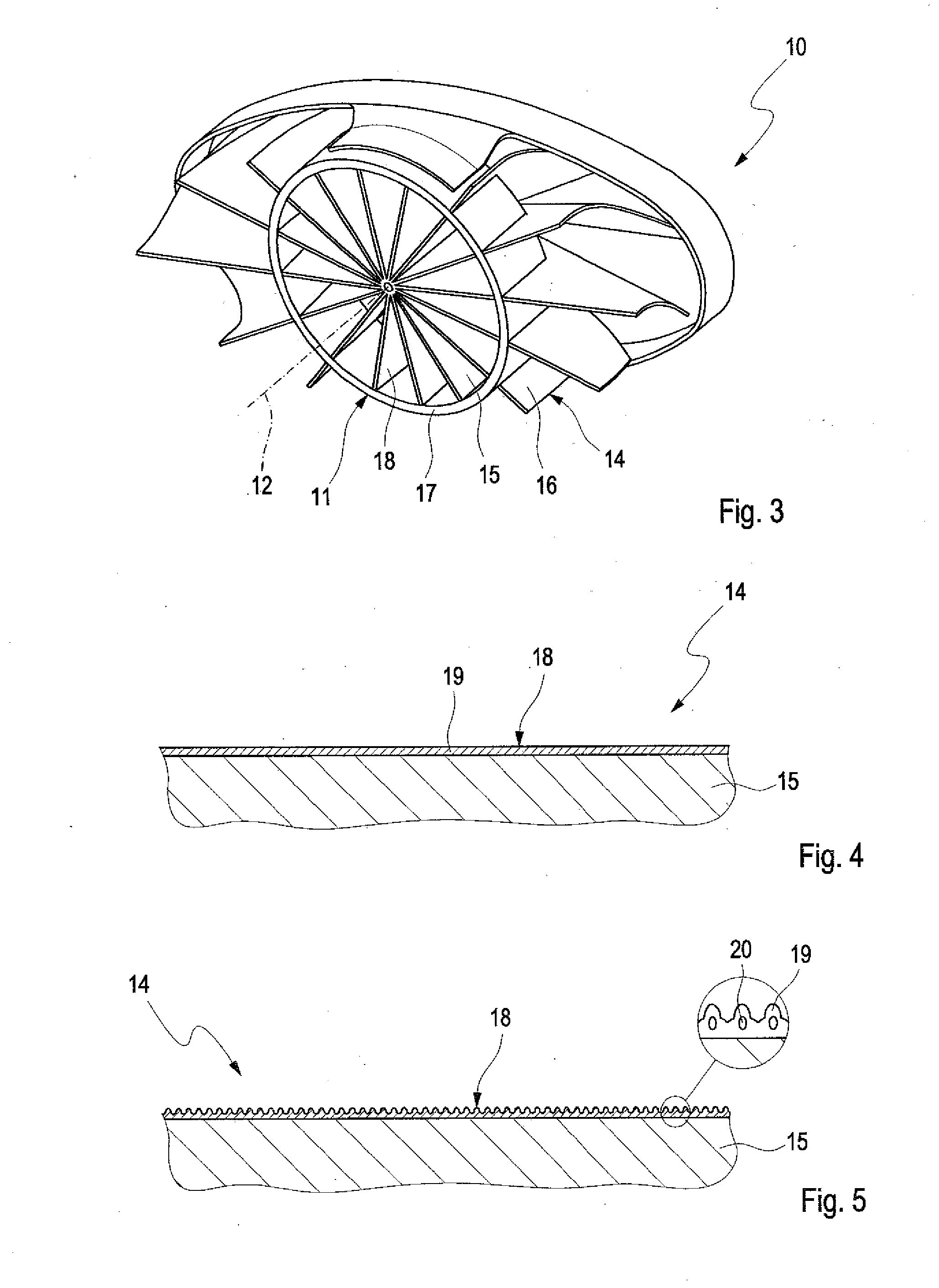
[0025]Throughout all the figures, same or corresponding elements may generally be indicated by same reference numerals. These depicted embodiments are to be understood as illustrative of the invention and not as limiting in any way. It should also be understood that the figures are not necessarily to scale and that the embodiments may be illustrated by graphic symbols, phantom lines, diagrammatic representations and fragmentary views. In certain instances, details which are not necessary for an understanding of the present invention or which render other details difficult to perceive may have been omitted.

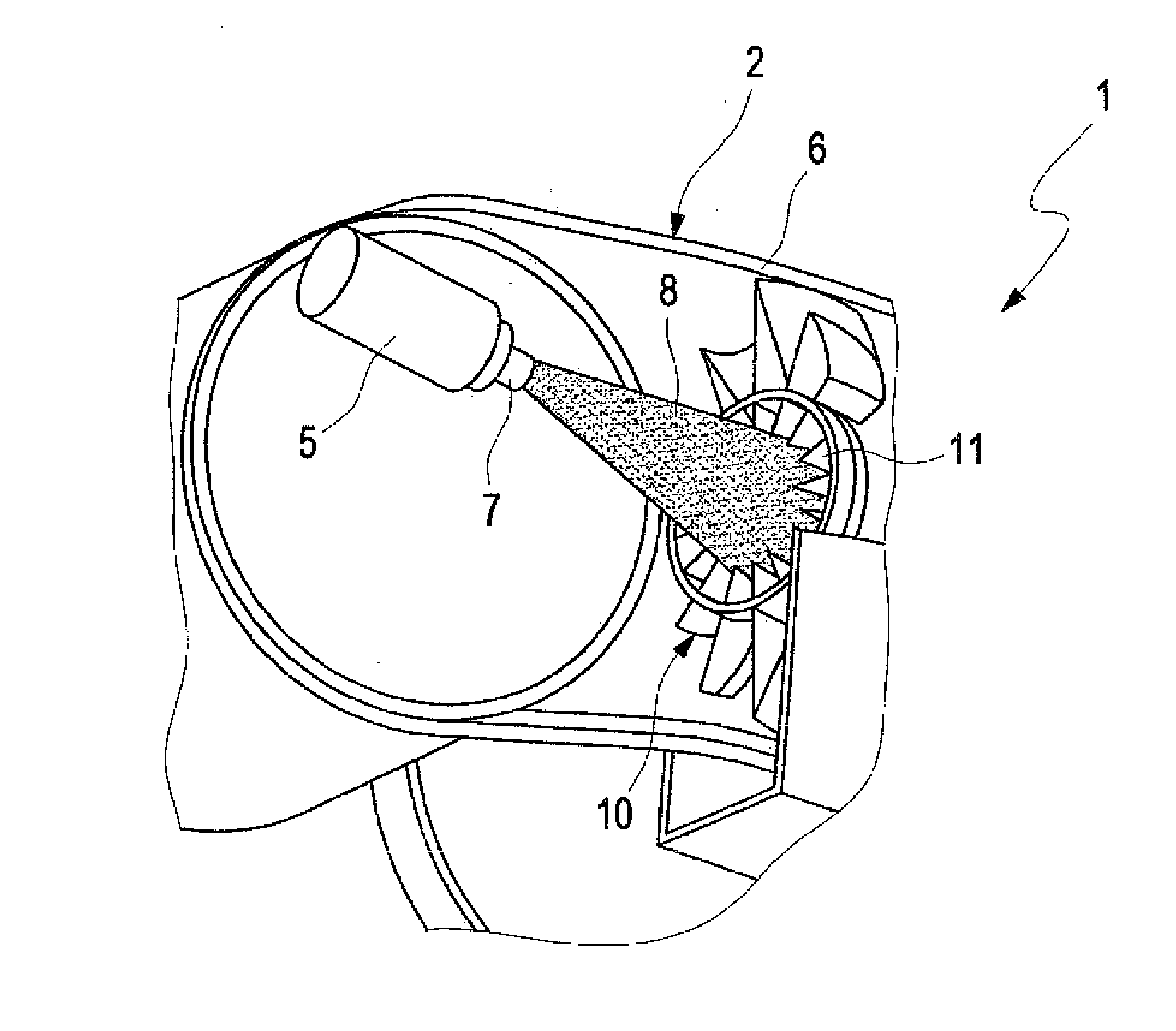
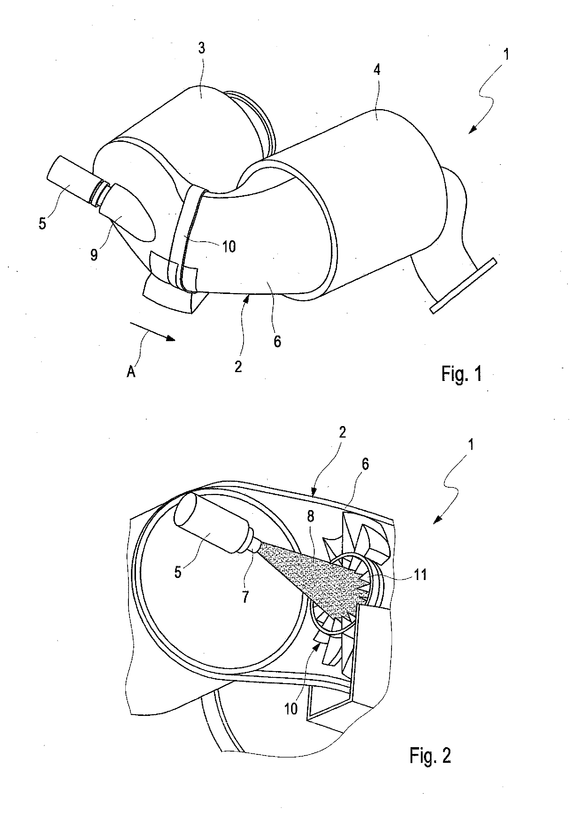
[0026]Turning now to the drawing, and in particular to FIG. 1, there is shown a perspective external view of components of an exhaust system according to the present invention, generally designated by reference numeral 1, for a motor vehicle having an internal combustion engine, e.g. a diesel internal combustion engine. The exhaust system 1 includes an exhaust pipe 2 sized to exten...


PUM

PropertyMeasurementUnit
thicknessaaaaaaaaaa
thicknessaaaaaaaaaa
temperaturesaaaaaaaaaa

Abstract

An exhaust system for an internal combustion engine includes an injection nozzle for injecting a liquid reductant into exhaust gas streaming through the exhaust system. A mixer is arranged in the exhaust-gas stream for swirling and dispersing the liquid reductant in the exhaust-gas stream. The mixer is provided with a heat-resistant, wear-resistant and corrosion-resistant non-stick coating which is made of a glass or ceramic material to promote rolling off of the reductant. A SCR catalyst is arranged downstream of the mixer for selective catalytic reduction of nitrogen oxides with the aid of the reductant or decomposition products of the reductant.

Description

CROSS-REFERENCES TO RELATED APPLICATIONS[0001]This application claims the priority of German Patent Application, Serial No. 10 2014 018 852.3, filed Dec. 17, 2014, pursuant to 35 U.S.C. 119(a)-(d), the disclosure of which is incorporated herein by reference in its entirety as if fully set forth herein.BACKGROUND OF THE INVENTION[0002]The present invention relates to an exhaust system of an internal combustion engine with mixer for a liquid reductant.[0003]The following discussion of related art is provided to assist the reader in understanding the advantages of the invention, and is not to be construed as an admission that this related art is prior art to this invention.[0004]Internal combustion engines, constructed as diesel internal combustion engine for example, nowadays use selective catalytic reduction (SCR) to decrease the nitrogen oxide fraction in exhaust systems of current motor vehicles. A liquid reductant, typically in the form of aqueous urea, also known as AdBlue, is ad...

Claims


Application Information

Patent Timeline
Patent Type & Authority Applications(United States)
IPC IPC(8): F01N3/20F01N3/28F01N13/16
CPCF01N3/2066F01N13/16F01N2530/02F01N2610/02F01N2530/24F01N3/2892F01N3/10F01N3/28F01N2510/08F01N2510/10F01N2610/1453Y02T10/12B01F23/2132B01F25/3141B01F25/4316B01F25/431974
Inventor WOHLFAHRT, DANNY
Owner AUDI AG
Why Eureka
Try Eureka