Enhanced roadway mark locator, inspection apparatus, and marker

a technology of inspection apparatus and roadway mark, which is applied in the direction of machinery control, processes, instruments, etc., can solve the problems of affecting and affecting the safety of workers, so as to improve the accuracy of roadway mark locators

Active Publication Date: 2016-07-21
LIMNTECH
View PDF9 Cites 51 Cited by
  • Summary
  • Abstract
  • Description
  • Claims
  • Application Information

AI Technical Summary

Benefits of technology

[0025]This application is intended to teach the use of sensor and data fusion algorithms for roadway mark locators, inspection apparatus and roadway markers for the roadway marking industry. In particular, this application teaches the use of Bayesian model-based filters in combination with a plurality of sensors for achieving more precise GPS geographical location data of a moving vehicle, and therefore any point located on the vehicle (offset corrected), thereby improving the accuracy of roadway mark locators, inspection apparatus and markers. This application discloses an apparatus for inputting raw GPS positional data (which may also include RTK enhanced raw GPS positional data) along with data derived from multiple sensors along with a kinematic model (i.e., a model based on the physical laws of motion) of the vehicle into a Bayesian model-based filter to fuse this data to achieve a more accurate GPS geographical location data of both the vehicle and roadway marks.

Problems solved by technology

Although the current technology achieves the desired goal of providing a system for applying roadway markings, the current system is manually intensive and places the personal safety of workers at significant risk.
During this time, traffic visibility is impeded and there is a significant potential for oncoming traffic to collide with those workers manually defining the starting and ending positions for each segment.
Unfortunately, these methods required the placement of transmitters along the roadway.
Again, this attempt proved difficult to implement because of sunlight interference.
There are many disadvantages with using radioactive marking material, including health and safety issues, longevity (half-life) of the radioactive material, and disposal problems.
This attempt requires that the drawing pattern for the roadway be predetermined and fails if the exact location of the roadway marking is inaccurately defined, or if the drawing pattern does not correspond exactly with the geographical position of the actual roadway.
The current roadway marking technology has at least several problems.
One problem is that a significant amount of manual labor is required to accurately paint lines on roadways, and as a result workers are placed in an unsafe working environment during the roadway marking process.
Another problem with 
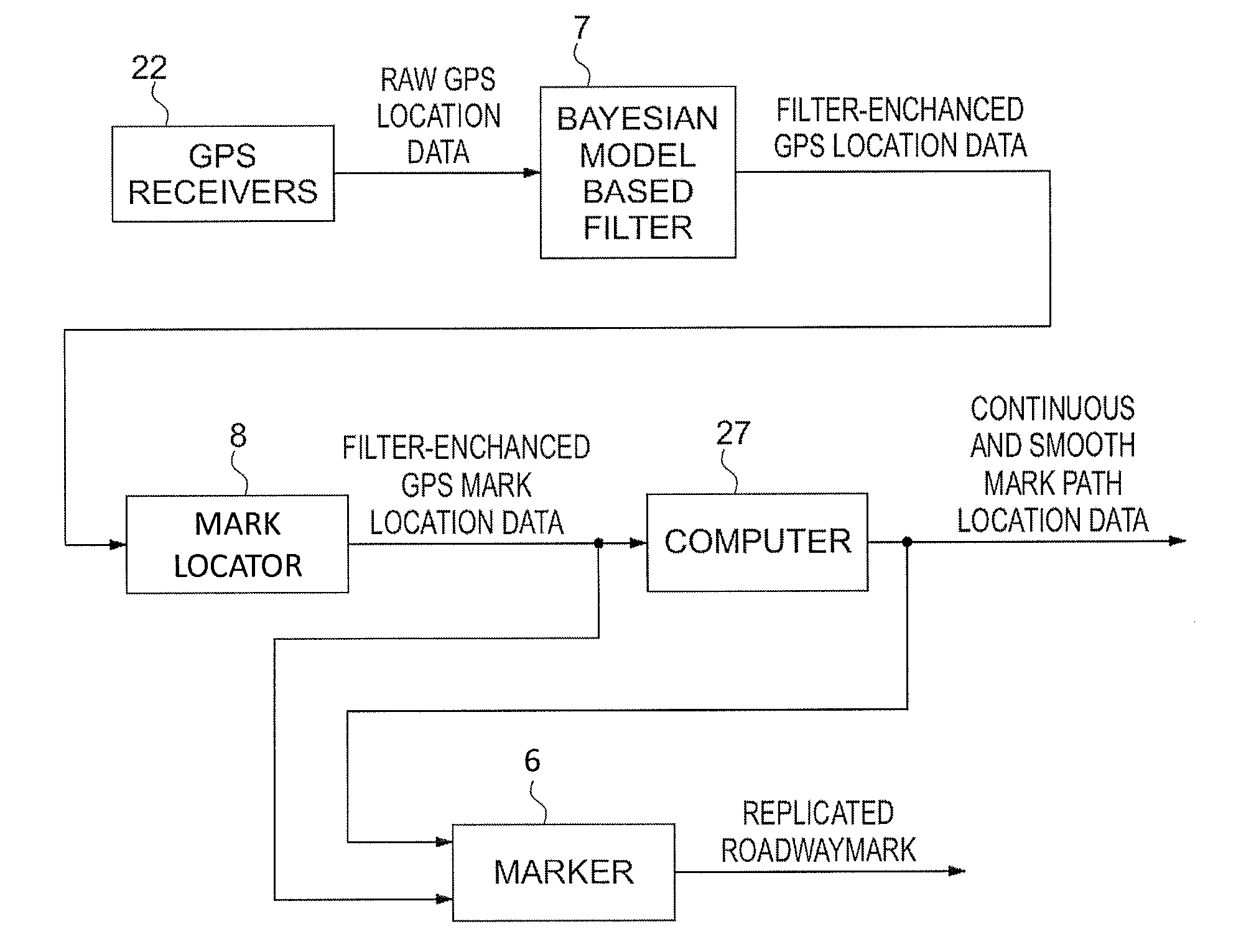
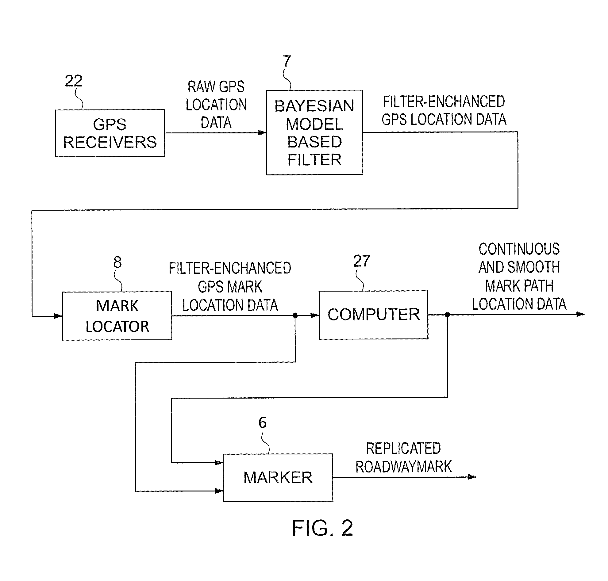
current technology is the inability to easily and quickly obtain sampled geographical coordinates of the existing roadway line marks using GPS or GPS-based pseudolite arrays.
A related problem is the inability to use this sampled data to generate a continuous function of the geographical coordinates for the entire mark path.
Additional problems are the lack of an offsetting capability to determine other substantially parallel mark paths for line marking and, therefore, the inability to uniformly deposit paint or other material along the first (or second) mark path duplicating the previous mark.
In the past even experienced machine operators have found it difficult to manually guide a road marking machine with sufficient accuracy even where old markings are available.
However, such attempts have not been wholly satisfactory because a break in the old marking does not give steering guidance during breaks.
Moreover, this approach is of no use whatsoever where the old marks have disappeared or for new markings.
However, these arrangements require transmitters to be placed along the road, and in the case of light beams, are degraded by the effect of sunlight.
However, this method suffers from the disadvantage that embedding the radiating material in the road surface can be costly.
Furthermore, radiating materials tend to lose their effectiveness after a time period.
Although Manning identifies certain disadvantages with the known roadway marking technology, the GPS-controlled paint spray system disclosed by Manning in the '693 and '934 patents has its own disadvantages.
The system fails if a discrepancy exists between the actual and drawing pattern road position.
In addition, the disclosed system cannot maintain the accurate horizontal registration of the paint markings which is required when the drawing pattern does not accurately match the actual constructed roadway.
This situation occurs where on-site construction changes are prompted by unforeseen construction problems.
Such problems include, for example, bedrock formations, unstable ground structure, water runoff, and the like.
Such selection does not allow for a smoothly constructed functional fit.
The '693 patent does not disclose any mechanism for producing a curved line.
This system is prone to positional inaccuracies of the operator and is not completely automated.
Individual selection of each roadway mark is time consuming and dependent upon the skill and experience of the operator.
Furthermore, no mechanism is provided to automatically inspect the roadway marks for reflectivity and contrast, length and width dimensions, mark fill percentage, and other important quality standards.
Additionally, vehicle-mounted roadway mark locators, inspection apparatus and marking systems which rely solely upon raw (i.e., not post-processed) GPS or GPS-based pseudolite array systems positional data are prone to many errors which may degrade the usefulness and accuracy of these systems.
However, if the reception of these signals are temporarily lost as the result of foliage obstructions, such as tree cover, or are lost as the result of the vehicle passing through a tunnel or other RF blocking obstruction, the GPS receiver fails to provide accurate geographical location data resulting in inaccurate roadway mark geographical location data.
Other sources of error exist and include the inherent random noise occurring during the reception of the GPS signals.
Although real time kinematic (RTK) enhanced GPS-based systems improve the accuracy of the GPS or GPS-based pseudolite systems to centimeter accuracy, errors still arise particularly in determining the GPS geographical location of moving vehicles from raw GPS positional data even with the improvements afforded by RTK enhanced raw GPS-based systems.
For example, RTK signal reception may be lost in addition to the GPS signals, thereby causing inaccurate geographical location data.
Moving vehicles are also prone to vibrations caused by pot holes and other roadway imperfections which may cause the GPS antenna to vibrate, yielding inaccurate determination of GPS geographical location data.
Vehicle suspension systems may also cause vibrations as the vehicle moves along a roadway.
Additionally, vehicle loads may change causing changes in the GPS antenna(s) location and therefore errors in determining the GPS location of the vehicle.
The dispensing process decreases the vehicle load and may cause changes in the roll and pitch of the vehicle, again causing changes in the GPS antenna(s) location.
Therefore the loss of either RTK and GPS signals or both along with vehicle vibrations may cause geographical location inaccuracies for those roadway mark locators, inspection systems and markers singularly dependent upon the reception of only RTK and GPS signals.

Method used


Image

  • Enhanced roadway mark locator, inspection apparatus, and marker
  • Enhanced roadway mark locator, inspection apparatus, and marker
  • Enhanced roadway mark locator, inspection apparatus, and marker

Examples


Embodiment Construction

[0074]The present invention provides Bayesian model-based filter-enhanced GPS-based systems used for painting or otherwise marking roadway traffic lane demarcation lines and vehicle-mounted locating and inspection systems for determining an accurate geographical location and condition of roadway marks. One type of a Bayesian model-based filter is, for example, a Kalman or Kalman-like filter. It is noted that other Bayesian model-based filters exist.

[0075]Referring now to the drawing, in which like reference numbers refer to like elements throughout the various figures that comprise the drawing, FIG. 1 shows a moving or self-propelled vehicle 1 which is located on a road or roadway 2 near a center mark line 3 applied to the surface of the roadway 2. Also shown is a roadway edge boundary line 4 and a vehicle-referenced Cartesian coordinate system 9.

[0076]The term “vehicle” used in this document is given its broadest meaning, including any conveyance, motorized device, or moving piece ...


PUM


Abstract

An apparatus for locating, inspecting, or placing marks on a roadway. The apparatus includes a GPS-based machine vision locator for sampling discrete geographical location data of a pre-existing roadway mark evident on the roadway. A computer may determine a continuous smooth geographical location function fitted to the sampled geographical location data. A marker is responsive to the GPS-based locator and geographical location function for replicating automatically the pre-existing roadway mark onto the roadway. The apparatus is typically part of a moving vehicle. A related method is disclosed for locating, inspecting, and placing marks on a resurfaced roadway. A similar apparatus can be used to guide a vehicle having a snow plow along a snow-covered roadway, or a paving machine along an unpaved roadway surface. The apparatus provides for accurate determination of roadway mark locations, roadway mark inspection apparatus and roadway markers using Bayesian model-based filtered enhanced GPS geographical location data.

Description

CROSS REFERENCE TO RELATED APPLICATIONS[0001]This application is a continuation-in-part of U.S. patent application Ser. No. 13 / 728,062, filed on Dec. 27, 2012, which is a continuation-in-part of U.S. patent application Ser. No. 13 / 351,829, filed on Jan. 17, 2012 and issued as U.S. Pat. No. 8,467,968 on Jun. 18, 2013. This application further claims priority to U.S. Provisional Patent Application No. 62 / 288,682 filed Jan. 29, 2016. All prior applications are incorporated by reference into this document, in their entirety and for all purposes.TECHNICAL FIELD[0002]The present invention relates generally to GPS-based machine vision locating and inspecting systems and to devices for making a visual indicia in or on top of pavement. More particularly, the present invention relates to a vehicle-mounted Bayesian model-based filter-enhanced GPS-based locating and inspecting systems for determining the geographical location and condition of roadway marks, and Bayesian model-based filter-enhan...

Claims


Application Information

Patent Timeline
Patent Type & Authority Applications(United States)
IPC IPC(8): G01S19/14B60R1/00E01C23/16E01H5/06G07C5/08G06V10/764
CPCG01S19/14E01H5/06G07C5/08B60R2300/804B60R1/00B60R2300/105B60R2300/302E01C23/163B62D5/0463G01C15/02F16M11/10F16M11/2071F16M13/02F16M2200/022E01C23/01G06V20/588G06V10/764G06F18/24155F16M13/022
Inventor DOLINAR, DOUGLAS D.HALLER, WILLIAM R.SMITH, MATTHEW W.STAHL, CHARLES C.
Owner LIMNTECH
Why Eureka
Try Eureka