Now at the beginning of the 21st century we face a number of problems that may threaten the human race and the ecosystems on the
planet.
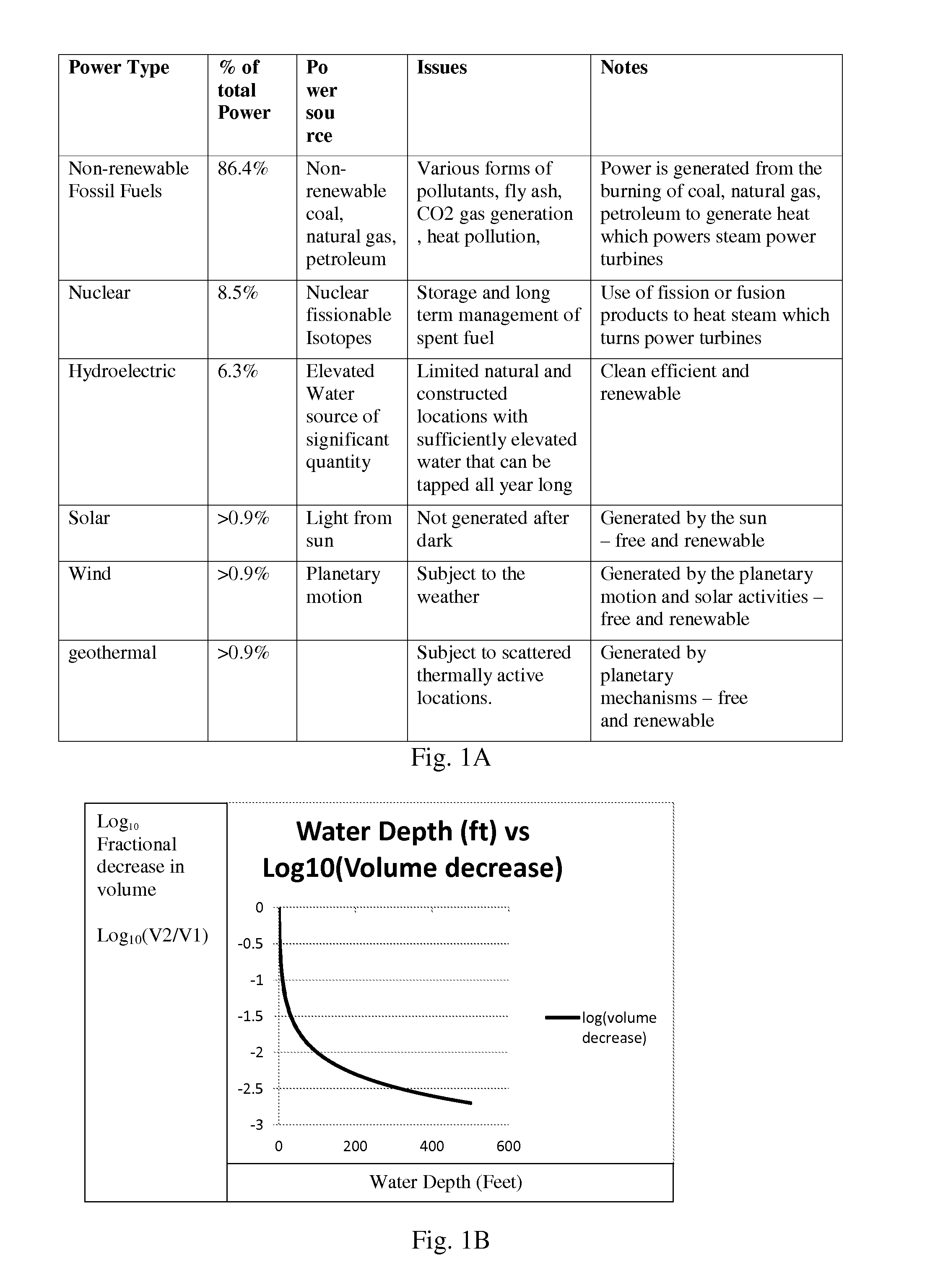
Fossil fuel generation also has drawbacks associated with limited availability and the cost of extracting and transporting the natural resources (i.e.
coal, oil, gas) to the power
plant location.
Nuclear power reactors on the other hand produce long and
short life nuclear waste products which must be stored and managed (long term) after the original fuel rods have become depleted.
Finally there is the ever present danger that a
nuclear reactor could become unstable or damaged, as was the case with Chernobyl Russian reactors, Three
Mile Island in the US, and the Fukushima-Daiichi reactors in Japan.
Solar energy, while renewable and clean, is subject to lack of availability during night time hours.
Similarly, energy from wind generation is not constantly available since it is subject to the unpredictability of
weather patterns.
For these reasons, many industrial experts do not considered solar and wind generation as truly viable replacements for fossil and nuclear generation plants.
Lastly geothermal and hydroelectric, while both clean and able to produce abundant power, are generally limited geographically to a few commercially feasible sites that can be made commercially productive.
Both devices utilize
buoyancy as the motive force, and do not make significant use of gravity.
The conclusion is that buoyancy embodiments which directly utilize compressed air, such as those illustrated by prior art discussed above, quickly become less effective and less efficient as the tank fluid depth /
water column height is increased (i.e. the power generated by compressed air does not scale well with
water depth).
The compressed air that is injected or transferred within the
system consumes energy, and the amount of energy expended increases with
water pressure and water height.
A further limitation of buoyancy devices, besides that fact that they do not scale well with
water depth, and the fact that they require relatively large expenditures of energy to operate (e.g. to compress air), is that they only take
advantage of the forces of buoyancy and generally do not take
advantage of the forces of gravity, as is done by a
water wheel, or a generalized gravity wheel.
A simple
energy analysis of this patent shows that the proposed device is non-functional.
While it may be possible to use buoyancy to lift a ball, and gravity to convert the height gained to energy via a gravity wheel, it must be done such that there is a
net energy gained, otherwise there is no possible energy that can be extracted from the system.
Hence it will be difficult if not impossible for the
piston to close with the ball above the water line even if there is no water leaking form the
piston housing.
With the
piston housing leaking enormous amounts of water under pressure, the ball will be pushed out of the
enclosure opening by the pressurized fluid flow, hence there is no way to force the ball into the piston without further mechanical means, which has not been disclosed by Francis.
The elevation of this leaked fluid requires an enormous amount of energy which must be subtracted from the
energy balance of the system.
The fluid that has leaked, if not replaced, will cause the buoyant fluid column to collapse and the
fluid pressure at the bottom of the fluid column to diminish.
Given that force of gravity produces in this case less than 1.2 pounds of force for each ball, even with the combined force from several ball drops, there is no possibility that the downward force of gravity can overcome the force of the flowing water
coming out of the piston
enclosure opening so as to insert the ball into the piston, nor is it possible for the “
drive wheel” to begin to turn without addition 108 pounds of external applied force and other associated mechanical means.
Decreasing the height of the
water column only reduces the height and potential energy that the ball can obtain.
This means the process as described always losses energy.
Clearly the process of
paragraph can never be used to generate power.
Hence its efficiency is worse than that of which is already producing a loss of 50% of the power generated by the ball when fully elevated.
1. The
ability to work, as far as it does, applies only to a “ball” or
spherical shaped buoyant-object that can roll down the various ramps, but fall vertically downward.
2. The device shown in Francis FIG. 2 is mechanically complicated which makes it subject to reliability problems and significant frictional losses due to the described gears and connections.
3. The energy wheel 208a only captures half of the energy gained by the ball, which we have shown takes a loss with each cycle of the device. That is, there is no means shown to convert the full potential energy gained by the buoyant ball's elevation into energy. As shown in Francis FIG. 2 only about half of the energy gained can be utilized since 208a is located half way up the device, and the other half (208b) must be used to drive the piston or implement some other means which has also been shown not to be workable. The
overall efficiency of the device of Francis FIG. 2 (if it really operated) goes down to 25% or less if the best process given by
paragraph is used to inject said ball. This means that in the best case, if Francis FIG. 2 could be made to work, 75% more energy must be supplied into the system for every ball cycled through the device. Since there is no
external source of power the embodiment will not function.
If multiple magnets are falling through the same coil at the same time, then there can be undesirable constructive and destructive interference of the electrical waveforms occurring with respect to the induction process.


