Light-Emitting Device and Luminaire Incorporating Same

Active Publication Date: 2016-07-28
QUARKSTAR
View PDF7 Cites 15 Cited by
  • Summary
  • Abstract
  • Description
  • Claims
  • Application Information

AI Technical Summary

Benefits of technology

[0009]Accordingly, the present technology provides light-emitting devices and luminaires having lenses of refractive index n with spherical refractive exit surfaces and that are designed to operate efficiently in conjunction with extended source luminous elements having, in some embodiments, a disk shape. This is accomplished by positioning the edge of the emitting surface of the luminous element on a notional sphere of radius R/n opposite the exit surface (or radius Rn0/n if the device is emitting into a medium of index no), so that at least a portion of the edge of the emitting surface is aplanatically imaged by the spherical exit surface. Aplanatic “sharp” imaging results in a well-controlled angular distribution of those edge rays that

Problems solved by technology

In this position, the phosphor is subjected to the high operating temperature of the semiconductor die, and it is difficult to design and fabricate a die package with excellent angular color uniformity.
But compared to the more point-like earlier-generation white LEDs, it is more difficult to design and manufacture efficient optics to tailor the light distribution from these extended-source luminous elements, especially for applications needing narrower beam patterns or steep cutoff at the beam edges.
Certain conventional approaches to making narrower or steeper patterns result in unwanted losses in efficiency, as some light from the luminous elements is blocked rather than redirected into the desired beam pattern.
Similarly, using conventional imaging optics to generate ima

Method used


Image

  • Light-Emitting Device and Luminaire Incorporating Same
  • Light-Emitting Device and Luminaire Incorporating Same
  • Light-Emitting Device and Luminaire Incorporating Same

Examples


Embodiment Construction

[0030]While the configuration and performance of various embodiments are discussed in detail below, it should be appreciated that the concepts described can be embodied in a wide variety of specific contexts. The specific embodiments discussed herein are thus merely illustrative of specific ways to make and use the invention and are not intended to delimit the scope of the invention.

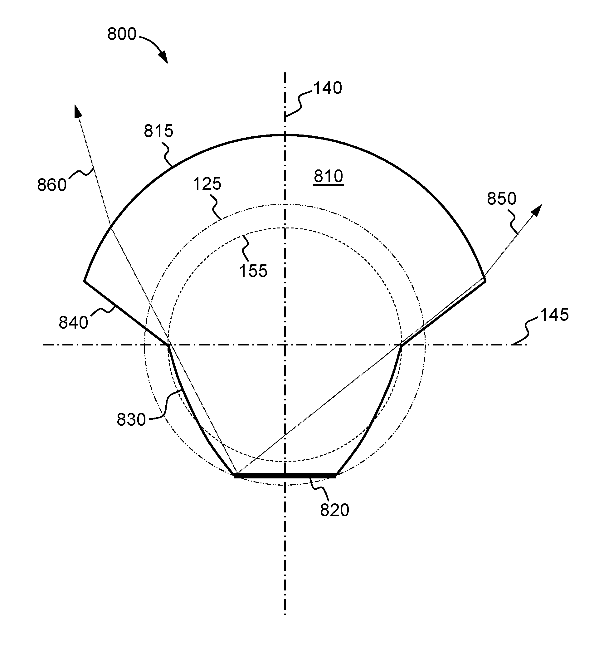
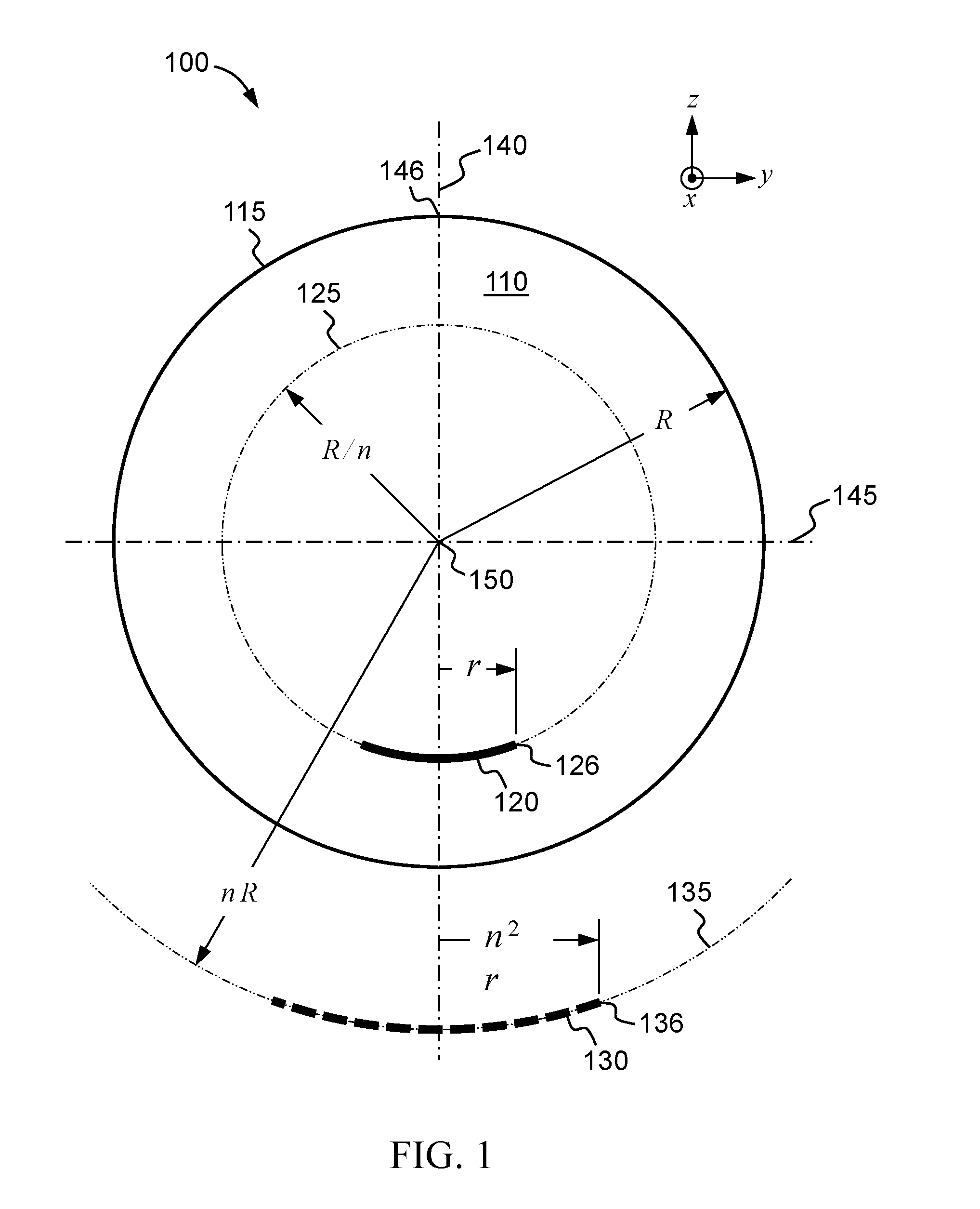
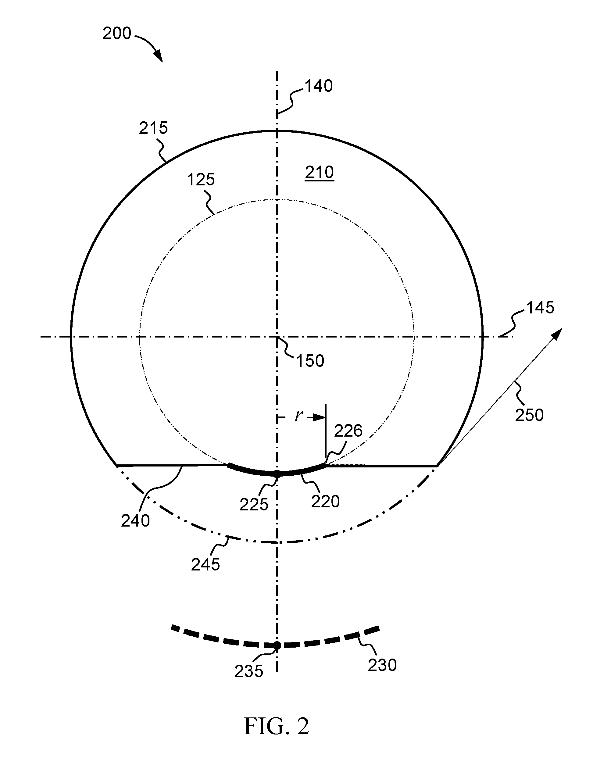
[0031]Nonimaging optical design depends primarily on the edge ray principle (W. Welford and R. Winston, The Optics of Nonimaging Concentrators, New York: Academic Press, 1978) to design optical systems having high optical efficiency. According to the edge ray principle, an ideal system (having maximum theoretical concentration and efficiency) transmitting radiation from an entry aperture to an exit aperture has the property that extreme rays of the entry aperture pass the exit aperture likewise as extreme rays. All other rays originating within the entry aperture traverse the system to lie at angles and / ...


PUM

PropertyMeasurementUnit
Fractionaaaaaaaaaa
Angleaaaaaaaaaa
Radiusaaaaaaaaaa

Abstract

A light-emitting device includes a lens of refractive index n having a spherical exit surface of radius R and a luminous element positioned such that at least a portion of an edge of an emitting surface of the luminous element lies on a sphere of radius R/n opposite the exit surface, whereby that portion of the edge of the emitting surface is aplanatically imaged by the spherical exit surface. The light-emitting device may further include one or more reflective sidewalls arranged to reflect a fraction of light emitted from the luminous element before it is refracted by the exit surface. A luminaire incorporating a housing and a light-emitting device of this type is also provided, which may include one or more additional optical elements such as reflectors or lenses to further direct and shape light from the light-emitting device.

Description

BACKGROUND[0001]1. Field of the Invention[0002]The present invention relates to light sources for illumination, and more particularly to light-emitting devices and luminaires having refracting and reflecting surfaces to alter the distribution of light from a luminous element.[0003]2. Description of the Related Art[0004]Light-emitting elements (LEEs) are ubiquitous in the modern world, being used in applications ranging from general illumination (e.g., light bulbs) to lighting electronic information displays (e.g., backlights and front-lights for LCDs) to medical devices and therapeutics. Solid state lighting (SSL) devices, which include light-emitting diodes (LEDs), are increasingly being adopted in a variety of fields, promising low power consumption, high luminous efficacy and longevity, particularly in comparison to incandescent and other conventional light sources. A luminaire is a lighting unit that provides means to hold, position, protect, and / or connect one or more light-emi...

Claims


Application Information

Patent Timeline
IPC IPC(8): F21V5/04F21V7/00F21V7/22F21V7/04
CPCF21V5/041F21V5/046F21V7/22F21V7/0091F21V7/041H01L33/58H01L33/60F21V7/30
Inventor SMITH, GEORGE E.GARDNER, ROBERT C.
Owner QUARKSTAR
Why Eureka
Try Eureka