
Secondary battery and electronic device

a technology of secondary batteries and electronic devices, applied in the direction of batteries, cell components, cell component details, etc., can solve the problems of easy damage to parts, concentrated stress on parts of external bodies, etc., and achieve the effects of suppressing sharp bending, alleviating the concentration of stress which generates wrinkles of the exterior body, and suppressing the generation of cracks in the external body

Active Publication Date: 2016-07-28
SEMICON ENERGY LAB CO LTD
View PDF7 Cites 20 Cited by
  • Summary
  • Abstract
  • Description
  • Claims
  • Application Information

AI Technical Summary

Benefits of technology

The present invention provides a power storage device and a secondary battery with a cushioning material around the electrodes to protect them from damage during bending. The cushioning material also reduces level differences between the regions where the electrodes and the cushioning material are located, which helps alleviate stress concentration and prevents wrinkles on the battery's exterior. This invention can provide a safer and more reliable power storage solution.

Problems solved by technology

In the case where a film which has lower strength than a metal can is used as an exterior body of a secondary battery, a current collector provided in a region surrounded by the exterior body, an active material layer provided on a surface of the current collector, or the like might be damaged when force is externally applied to the secondary battery.
When the secondary battery is bent, however, stress is concentrated on part of the external body and the part might be easily damaged.

Method used


Image

  • Secondary battery and electronic device
  • Secondary battery and electronic device
  • Secondary battery and electronic device

Examples


embodiment 1

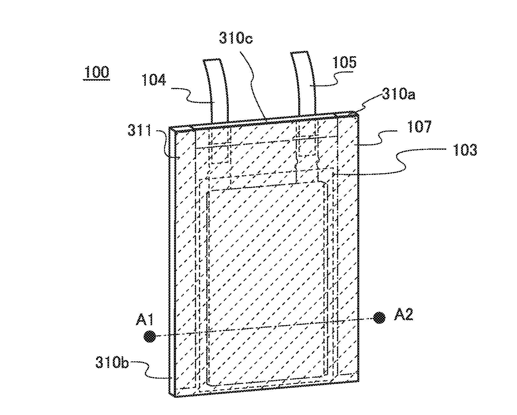
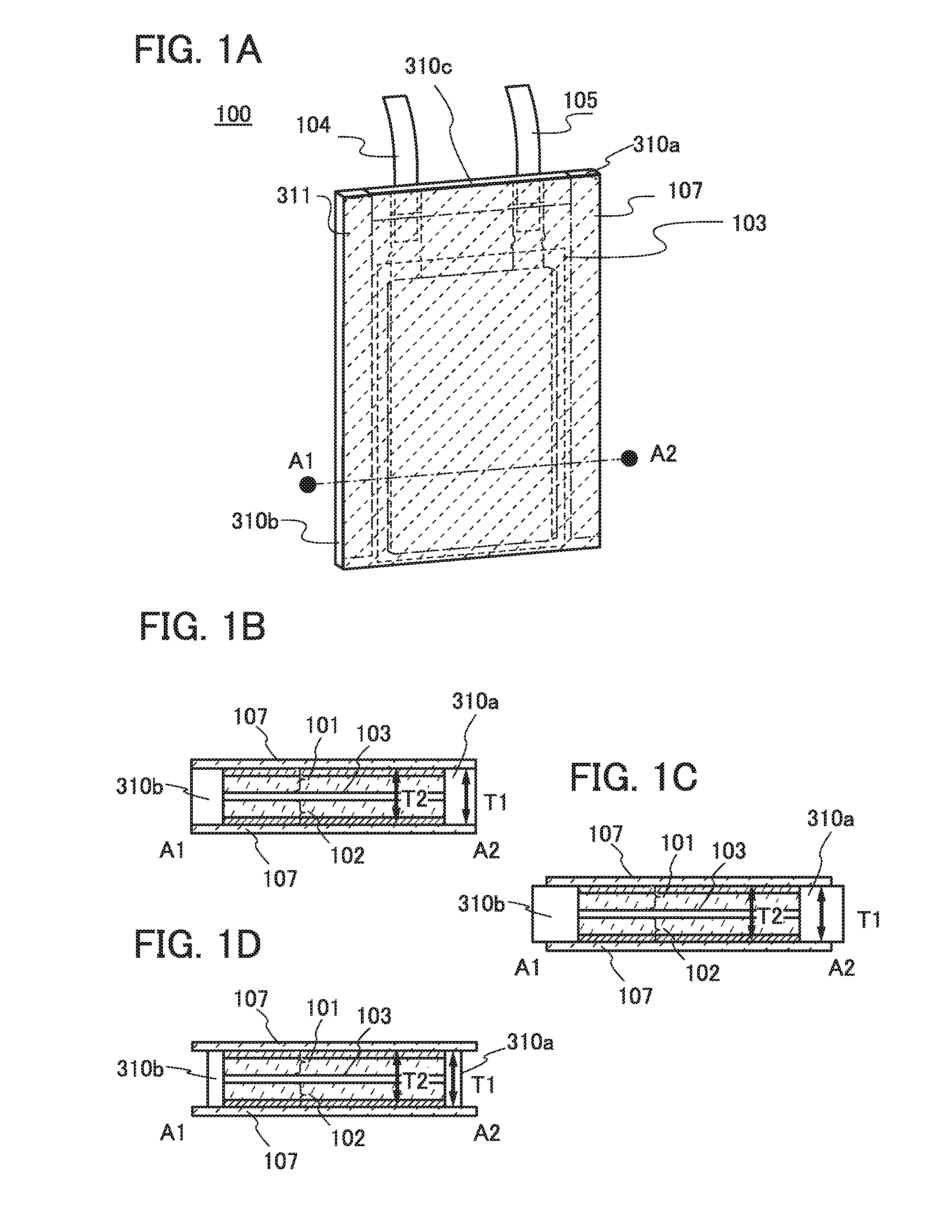
[0058]FIG. 1A is an example of a schematic view of a secondary battery. FIGS. 1B to 1D each illustrate an example of the internal structure surrounded by an exterior body of the secondary battery.

[0059]A secondary battery 100 of one embodiment of the present invention includes at least a positive electrode 101, a separator 103, a negative electrode 102, a cushioning material, and an electrolytic solution in a region surrounded by an exterior body 107. The secondary battery can have any of a variety of structures, and a film is used for the exterior body 107 in this embodiment.

[0060]A film used for the exterior body 107 is a single-layer film selected from a metal film (a film of a metal in the form of foil, such as aluminum, stainless steel, nickel steel, gold, silver, copper, titanium, nichrome, iron, tin, tantalum, niobium, molybdenum, zirconium, or zinc, or an alloy thereof), a plastic film formed of an organic material, a hybrid material film containing an organic material (e.g....

embodiment 2

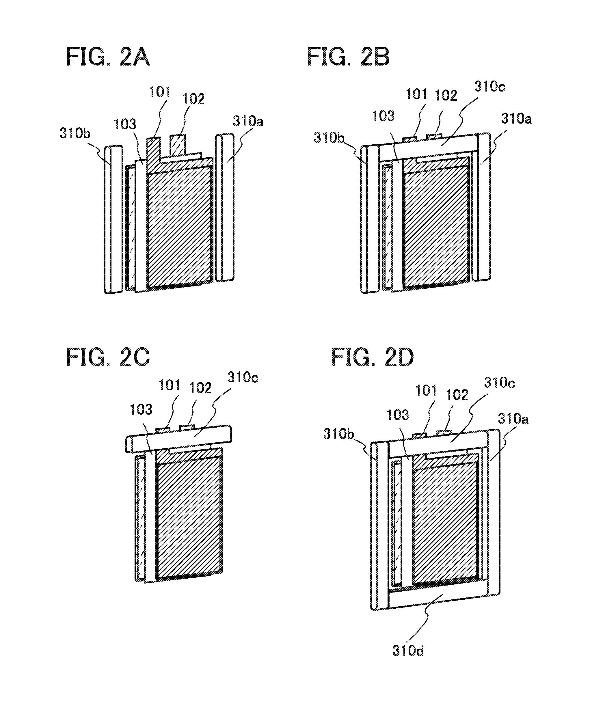
[0117]In this embodiment, unevenness is formed on a film serving as an exterior body by pressing, e.g., embossing, first, second, and third cushioning materials 312a. 312b, and 310c are provided in a region sandwiched by the exterior body, an elastic body (elastic material) whose cross section has a rectangular wave shape is used for each of the first and second cushioning materials 312a and 312b, and a columnar elastic body is used for the third cushioning material 310c.

[0118]In this embodiment, an example of fabricating a lithium-ion secondary battery with the use of a film whose surface is embossed with a pattern is described with reference to FIGS. 5A to 5E. Note that in FIGS. 5A to 5E, the same reference numerals are used for the same parts as those in FIGS. 1A to 1D, and detailed description of the parts is omitted for simplicity.

[0119]First, a sheet formed of a flexible material is prepared. As the sheet, a stack. i.e., a metal film provided with an adhesive layer (also refe...

embodiment 3

[0135]In this embodiment, an example of a secondary battery different from those in the above embodiments will be described with reference to FIGS. 14A to 14C, FIGS. 15A and 15B, and FIG. 16.

[0136]A secondary battery 200 illustrated in FIGS. 14A to 14C, FIGS. 15A and 15B, and FIG. 16 includes at least a stack of electrode groups including a plurality of positive electrodes 211 and a plurality of negative electrodes 215. The secondary battery 200 further includes a positive electrode lead 221 electrically connected to the plurality of positive electrodes 211 and a negative electrode lead 225 electrically connected to the plurality of negative electrodes 215. The positive electrodes 211 are each covered with a separator 203.

[0137]The secondary battery 200 includes an external body 207 covering the stack of electrode groups. The secondary battery 200 also includes an electrolytic solution 204 in a region covered by the exterior body 207.

[0138]The secondary battery 200 includes, as a cu...


PUM

PropertyMeasurementUnit
thicknessaaaaaaaaaa
thicknessaaaaaaaaaa
thicknessaaaaaaaaaa

Abstract

In the case where a film having lower strength than a metal can is used as an exterior body of a secondary battery, a current collector provided in a region surrounded by the exterior body, an active material layer provided on a surface of the current collector, or the like might be damaged when force is externally applied to the secondary battery. A secondary battery resistant to external force is provided. A cushioning material is provided in a region sandwiched by an exterior body of the secondary battery. Specifically, the cushioning material is provided on the periphery of an electrode group including a positive electrode current collector, a positive electrode active material layer formed on at least one surface of the positive electrode current collector, a separator, a negative electrode current collector, and a negative electrode active material layer formed on at least one surface of the negative electrode current collector.

Description

BACKGROUND OF THE INVENTION[0001]1. Field of the Invention[0002]One embodiment of the present invention relates to an object, a method, or a manufacturing method. One embodiment of the present invention relates to a process, a machine, manufacture, or a composition of matter. One embodiment of the present invention relates to a semiconductor device, a display device, a light-emitting device, a power storage device, a lighting device, an electronic device, or a manufacturing method thereof. In particular, one embodiment of the present invention relates to an electronic device and its operating system.[0003]Note that electronic devices in this specification generally mean devices including secondary batteries, and electro-optical devices including secondary batteries, information terminal devices including secondary batteries, and the like are all electronic devices.[0004]2. Description of the Related Art[0005]Portable electronic devices and wearable electronic devices have been activ...

Claims


Application Information

Patent Timeline
Patent Type & Authority Applications(United States)
IPC IPC(8): H01M2/02H01M10/0525H01M50/105H01M50/119H01M50/121H01M50/122H01M50/124H01M50/186H01M50/193H01M50/528
CPCH01M2/0202H01M2220/30H01M10/0525H01M50/105H01M50/121H01M50/186H01M50/193H01M50/124H01M50/122H01M50/119
Inventor TAKAHASHI, MINORUSUZAWA, DAISUKEUTO, NOZOMI
Owner SEMICON ENERGY LAB CO LTD
Learn More