
Method for measuring performance parameters and detecting bad pixels of an infrared focal plane array module

a technology of infrared focal plane array and performance parameters, which is applied in the field of measuring performance parameters detecting bad pixels of can solve the problems of inability to accurately assess and analyze performance index parameters, the error of offset value methods for infrared focal plane arrays with two, and the inability to uniformly respond to the output value of each pixel in the infrared focal plane array. to achieve the effect o

Active Publication Date: 2016-08-11
CUNLTD OPTICS CORP
View PDF24 Cites 10 Cited by
  • Summary
  • Abstract
  • Description
  • Claims
  • Application Information

AI Technical Summary

Benefits of technology

The present invention provides methods for accurately measuring performance parameters and detecting bad pixels in an infrared focal plane array (IRFPA) module. This allows for high-precision image division processing and the identification of bad pixels in multiple response areas. As a result, accuracy in measuring performance parameters and detecting bad pixels can be increased, reducing errors and improving overall performance.

Problems solved by technology

In reality, the responsivity values from the output of each pixel in the infrared focal plane array are not uniform for the sake of the semiconductor manufacturing process or the nature of semiconductors.
The different response areas (with higher responsivity values and lower responsivity values) and bad pixels all increase spatial noise and temporal noise of the infrared focal plane array and affect imaging quality of the infrared focal plane array to result in errors in assessment and analysis of performance index parameters, such as minimum resolvable temperature difference, spatial resolution, noise equivalent temperature difference, operability and the like.
The offset value method is not appropriate for infrared focal plane array with two or more than two response areas.
From FIGS. 15A and 15B, the offset value method is not good for infrared focal plane array with two or more than two response areas.
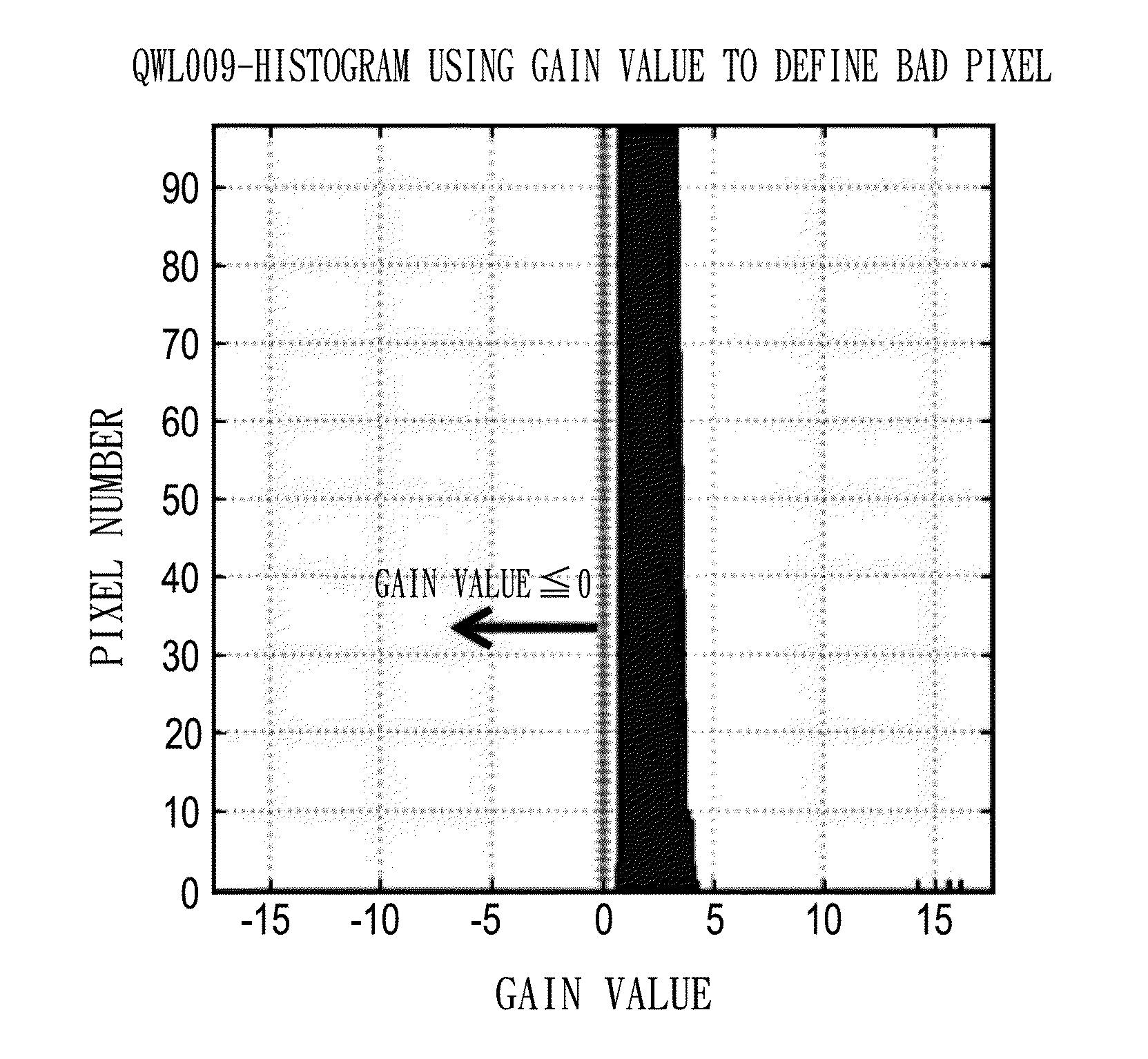
From FIGS. 16A and 16B, the gain value method is not good for infrared focal plane array with two or more than two response areas.

Method used


Image

  • Method for measuring performance parameters and detecting bad pixels of an infrared focal plane array module
  • Method for measuring performance parameters and detecting bad pixels of an infrared focal plane array module
  • Method for measuring performance parameters and detecting bad pixels of an infrared focal plane array module

Examples


Embodiment Construction

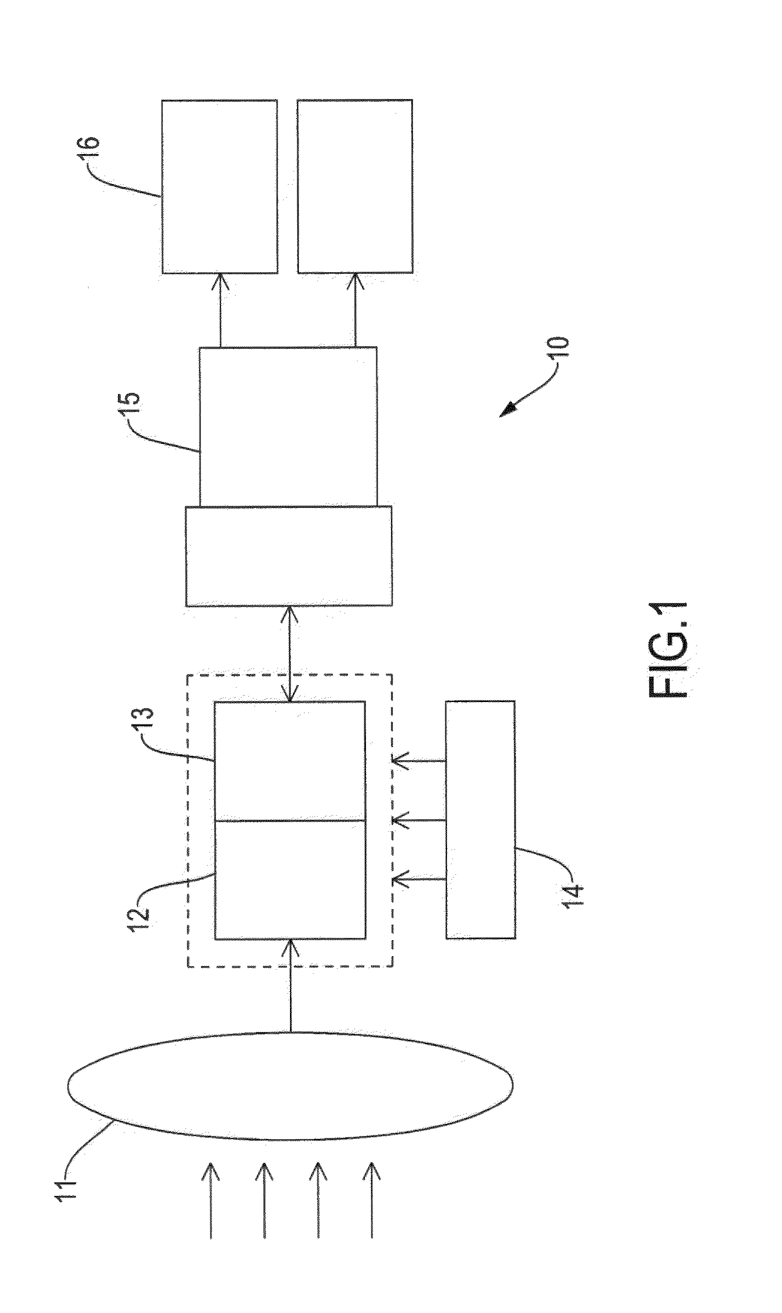
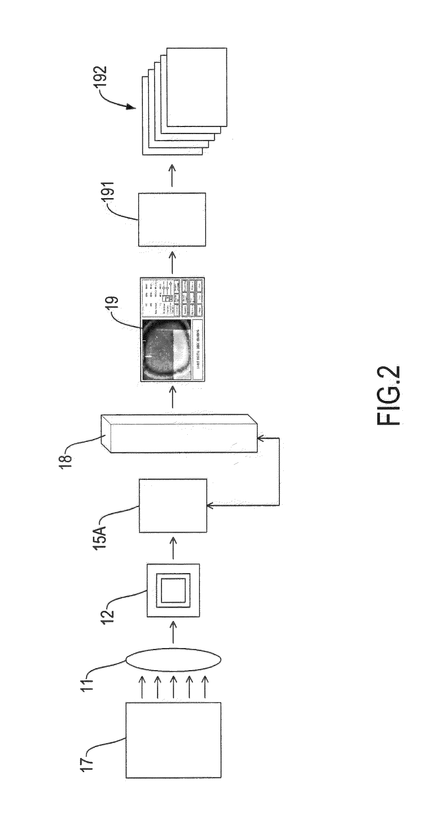
[0061]With reference to FIGS. 1 to 3, an infrared imaging camera 10 adopts a quantum well infrared (IR) imaging camera unit, which includes an IR lens 11, an infrared focal plane array (IRFPA) module 12, a readout integrated circuit (ROIC) 13, a cooler 14, and a video processing board 15. The video processing board 15 is electrically connected to a display 16. The display 16 serves to display infrared images. The cooler 14 serves to cool down temperature of the IRFPA module 12 for the IRFPA module 12 to correctly receive infrared light signals. In the present embodiment, the IRFPA module 12 has an array of pixels, which are 320×256 pixels, and the detection wavelength is in a range of 7.7-9.4 μm. With reference to FIG. 2, the IRFPA module 12 has an IR lens 11 facing a black body radiation source 17 (an object). The IRFPA module 12 is electrically connected to an infrared video processing board 15A. The infrared video processing board 15A has the ROIC 13 and the video processing boar...


PUM


Abstract

A method for measuring performance parameters of an infrared focal plane array (IRFPA) module has steps of capturing continuous digital images from the IRFPA module, performing image division on each of the continuous digital images, and measuring multiple performance parameters of each divided digital image, including signal transmission function, a temporal noise equivalent temperature difference, a spatial noise equivalent temperature difference, non-uniformity and operability, thereby increasing accuracy in measuring the performance parameters of the IRFPA module. Also, a method for detecting bad pixels of an IRFPA module includes a gain value method, an offset value method, a temporal noise method and a spatial noise method, is applicable to the IRFPA module with more than two response areas, and avoids incorrect detection to treat pixels in different response areas as bad pixels.

Description

BACKGROUND OF THE INVENTION[0001]1. Field of the Invention[0002]The present invention relates to a method for measuring performance parameters of an infrared focal plane array module and a method for detecting bad pixels of an infrared focal plane array module, and, more particularly, to a method with enhanced accuracy in measuring performance parameters of an infrared focal plane array module and a detection method capable of accurately identifying bad pixels.[0003]2. Description of the Related Art[0004]Infrared light is invisible to the human eyes while the energy of infrared light radiated from an object can be measured by an infrared detector. The voltage values and current values obtained from the measurement of the infrared detector can be converted into a gray level image or a virtual color image to be displayed on a display for the human eyes to see. Although visible light images can be seen by the human eyes only when there is sufficient background light source, instead of ...

Claims


Application Information

Patent Timeline
IPC IPC(8): H04N17/00G06K9/62G06T7/00H04N5/33
CPCH04N17/002H04N5/33G06T2207/30168G06T7/00G06T2207/20021G06K9/6215G06T7/0002G06T2207/10048H04N25/68H04N23/20G06F18/22
Inventor CHIU, YU-CHIAOCHANG, LE-YENCHEN, YIM-MIN
Owner CUNLTD OPTICS CORP
Learn More