
Light emitting diode

a technology of light-emitting diodes and junctions, which is applied in the direction of basic electric elements, electrical apparatus, and semiconductor devices, can solve the problems of deteriorating the luminous efficacy of light-emitting diodes, inefficient heat discharge, and increasing the junction temperature of light-emitting diodes, so as to prevent the reduction of output and improve yield

Active Publication Date: 2016-08-25
SEOUL VIOSYS CO LTD
View PDF35 Cites 5 Cited by
  • Summary
  • Abstract
  • Description
  • Claims
  • Application Information

AI Technical Summary

Benefits of technology

This patent describes a new design for a light emitting diode (LED) that can improve its performance. The design includes a larger area of light emission by removing a metal layer, which increases the efficacy of the LED. The design also reduces metal stress caused by contact, which improves the yield of the LED. Additionally, the design includes a line electrode that prevents uneven light emission at the edges of the LED, resulting in more uniform light emission across the entire LED. Overall, this new LED design has improved output and yield compared to previous designs.

Problems solved by technology

Further, lateral arrangement of the electrodes may cause current crowding, thereby deteriorating luminous efficacy of the light emitting diode.
Moreover, a sapphire substrate may be generally used as a growth substrate for lateral type light emitting diodes, which may cause inefficient heat discharge due to low thermal conductivity thereof.
As such, the lateral type light emitting diode may increase junction temperature of the light emitting diode and deteriorate an internal quantum efficiency thereof.
However, the electrode pad may be damaged by oxidation and the like during manufacturing of the light emitting diode having such structure, which may increase contact resistance and forward voltage.
Accordingly, the light emitting diode may have reduction in output, which may deteriorate reliability and lifespan of the light emitting diode.

Method used


Image

  • Light emitting diode
  • Light emitting diode
  • Light emitting diode

Examples


Embodiment Construction

[0027]In the following description, for the purposes of explanation, numerous specific details are set forth in order to provide a thorough understanding of various exemplary embodiments. It is apparent, however, that various exemplary embodiments may be practiced without these specific details or with one or more equivalent arrangements. In other instances, well-known structures and devices are shown in block diagram form in order to avoid unnecessarily obscuring various exemplary embodiments.

[0028]In the accompanying figures, the size and relative sizes of layers, films, panels, regions, etc., may be exaggerated for clarity and descriptive purposes. Also, like reference numerals denote like elements.

[0029]When an element or layer is referred to as being “on,”“connected to,” or “coupled to” another element or layer, it may be directly on, connected to, or coupled to the other element or layer or intervening elements or layers may be present. When, however, an element or layer is re...


PUM


Abstract

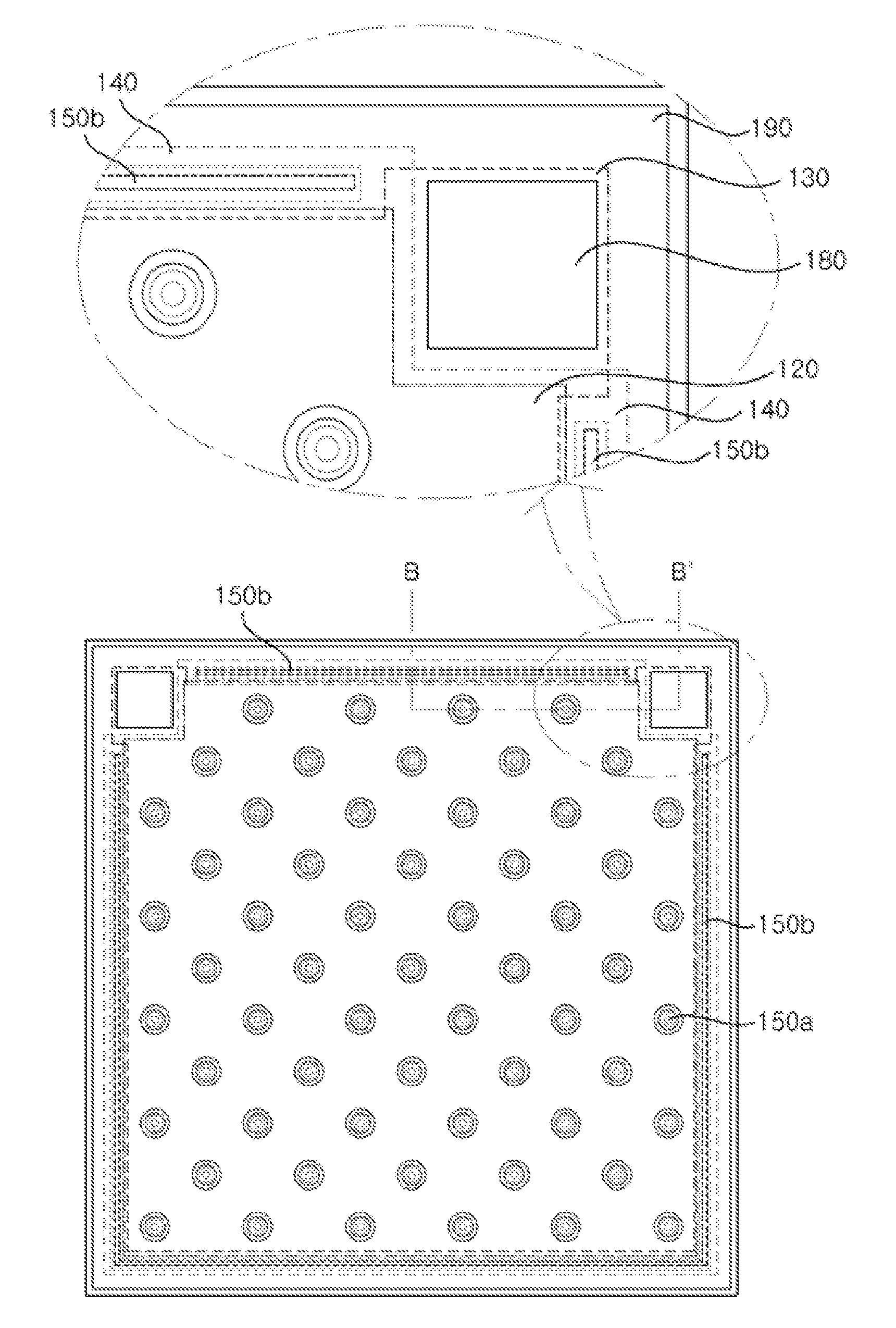
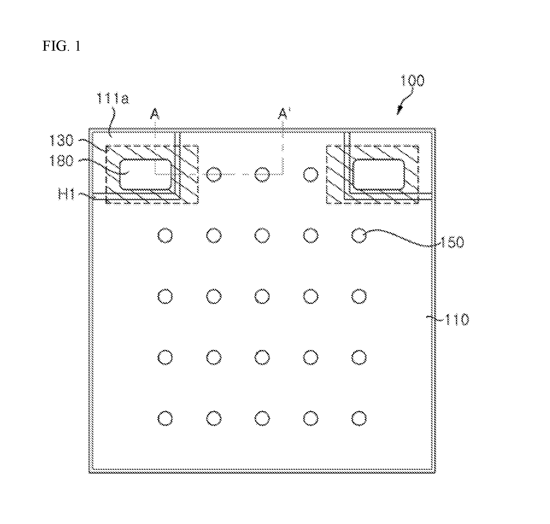
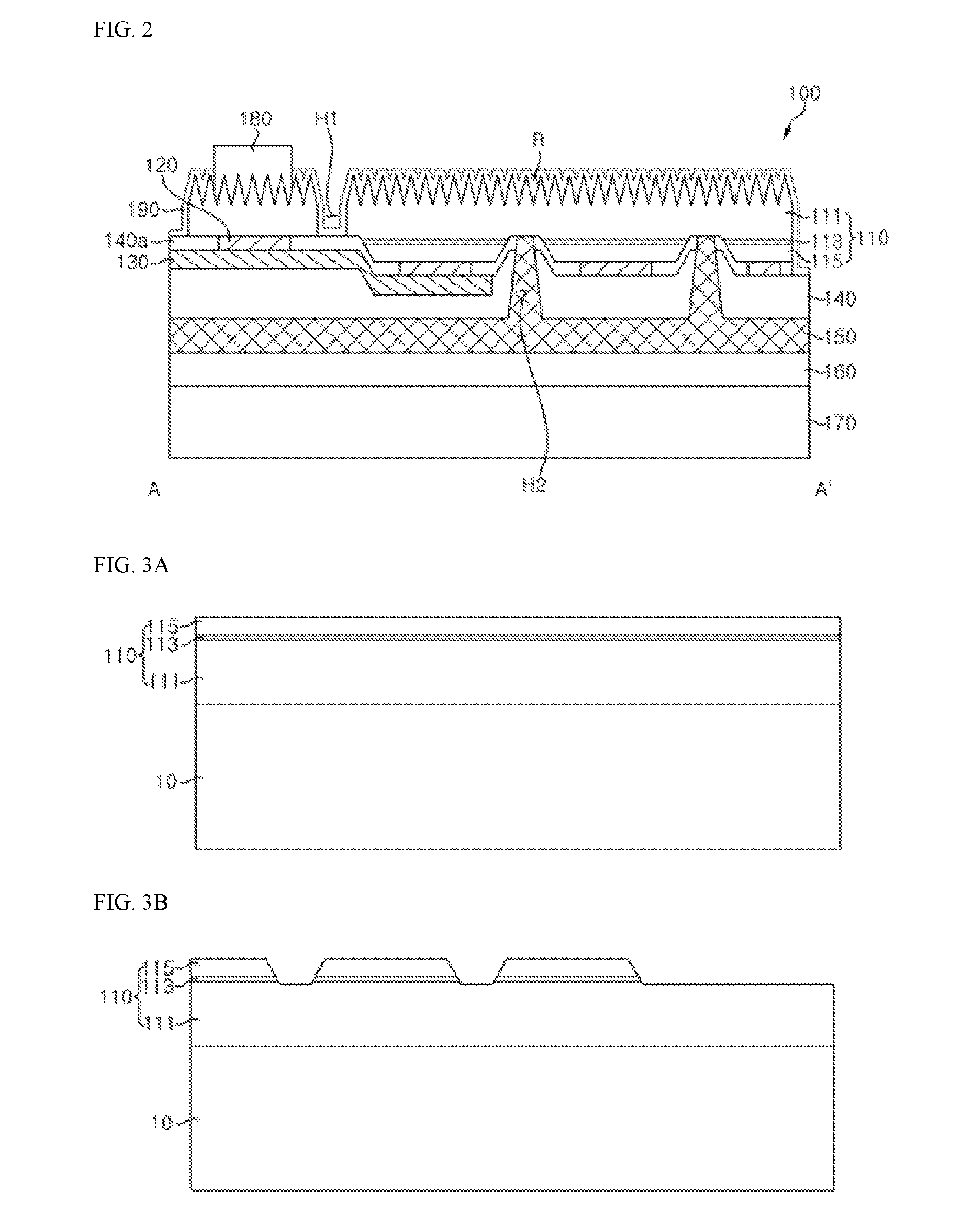
A light emitting diode includes a light emitting structure including first and second conductive type semiconductor layers and an active layer disposed therebetween, a second hole formed through the active layer and the second conductive type semiconductor layer, and exposing the first conductive type semiconductor layer, a reflective metal layer contacting a portion of the light emitting structure, a cover metal layer contacting at least a portion of the reflective metal layer, a first insulation layer covering the reflective metal layer and the cover metal layer, an electrode layer disposed on the first insulation layer, the electrode layer covering the first insulation layer and filling the second hole, an electrode pad disposed on the light emitting structure, and a first hole formed through the first conductive type semiconductor layer and corresponding to the cover metal layer, in which the electrode pad overlaps the cover metal layer.

Description

CROSS-REFERENCE TO RELATED APPLICATIONS[0001]This application is a continuation of International Application PCT / KR2015 / 010137, filed on Sep. 24, 2015, and claims priority from and the benefit of Korean Patent Application No. 10-2014-0129009, filed on Sep. 26, 2014, and Korean Patent Application No. 10-2015-0054554, filed on Apr. 17, 2015, which are incorporated by reference for all purposes as if fully set forth herein.BACKGROUND[0002]1. Field[0003]Exemplary embodiments relate to a light emitting diode, and more particularly, to a light emitting diode including an embedded electrode layer.[0004]2. Discussion of the Background[0005]A light emitting diode is an inorganic semiconductor device that generates light through recombination of electrons and holes. Such a light emitting diode may be used in various fields including displays, vehicle lamps, general lighting, and the like, and an application range of the light emitting diode has expanded.[0006]As for the light emitting diode, ...

Claims


Application Information

Patent Timeline
IPC IPC(8): H01L33/36H01L33/32H01L33/00H01L33/46
CPCH01L33/36H01L33/46H01L2933/0025H01L33/0075H01L2933/0016H01L33/32H01L33/22H01L33/382H01L33/0093H01L33/405
Inventor LEE, JOON HEELEE, MI HEE
Owner SEOUL VIOSYS CO LTD
Learn More