Fuel cell system

Active Publication Date: 2016-08-25
NISSAN MOTOR CO LTD
View PDF6 Cites 11 Cited by
  • Summary
  • Abstract
  • Description
  • Claims
  • Application Information

AI Technical Summary

Benefits of technology

[0009]According to an aspect of the present invention, there is provided a fuel cell system configured to generate an electric power by supplying an anode gas and a cathode gas to a fuel cell. The fuel cell system includes a connection line configured to connect the fuel cell to an electric load, and a converter connected to the connection line and a battery, the converter being configured to adjust a voltage of the connection line. The fuel cell system calculates a target output current of the fuel cell in accordance with a load of the electric load; carries out a switching control for the converter in accordance with the target output current; and controls a flow rate of the cathode gas to be supplied to the fuel cell in accordance with the target output current. At this time, the fuel cell system sets up an upper limit to the target output current on the basis of a generated electric power of the fuel cell and a guaranteed minimum voltage of the connection line for ensuring performance of the fuel cell and the electric load.
[0010]According to this aspect, an output current value by which the voltage of the connection line does not fall below the guaranteed minimum voltage is set up as the upper limit of the target output current on the basis of the generated electric power of the fuel cell and the guaranteed minimum voltage of the connection line. Then, on the basis of the target output current to which this upper limit is set up, the voltage of the connection line is adjusted by means of the switching control, and the flow rate of the cathode gas to be supplied to the fuel cell is controlled.
[0011]This makes it possible to set up the target output current for the converter so that the voltage of the connection line does not fall below the guaranteed minimum voltage. Since the flow rate of the cathode gas is also controlled on the basis of this target output current, it is possible to supply, to the fuel cell, the cathode gas with an appropriate flow rate according to an actual output current while keeping the guaranteed minimum voltage.

Problems solved by technology

As a result, it found that the following problem occurs.

Method used


Image

  • Fuel cell system
  • Fuel cell system
  • Fuel cell system

Examples


first embodiment

[0020]In a fuel cell, an electrolyte membrane is sandwiched between an anode electrode (fuel electrode) and a cathode electrode (oxidant electrode), and electric power is generated by supplying an anode gas (fuel gas) containing hydrogen to the anode electrode and supplying a cathode gas (oxidant gas) containing oxygen to the cathode electrode. Electrode reactions that proceed on both the anode electrode and the cathode electrode are as follows.

Anode Electrode: 2H2→4H++4e−  (1)

Cathode Electrode: 4H++4e−+O2→2H2O   (2)

[0021]The fuel cell generates an electromotive force of about one volt by means of these electrode reactions (1) and (2).

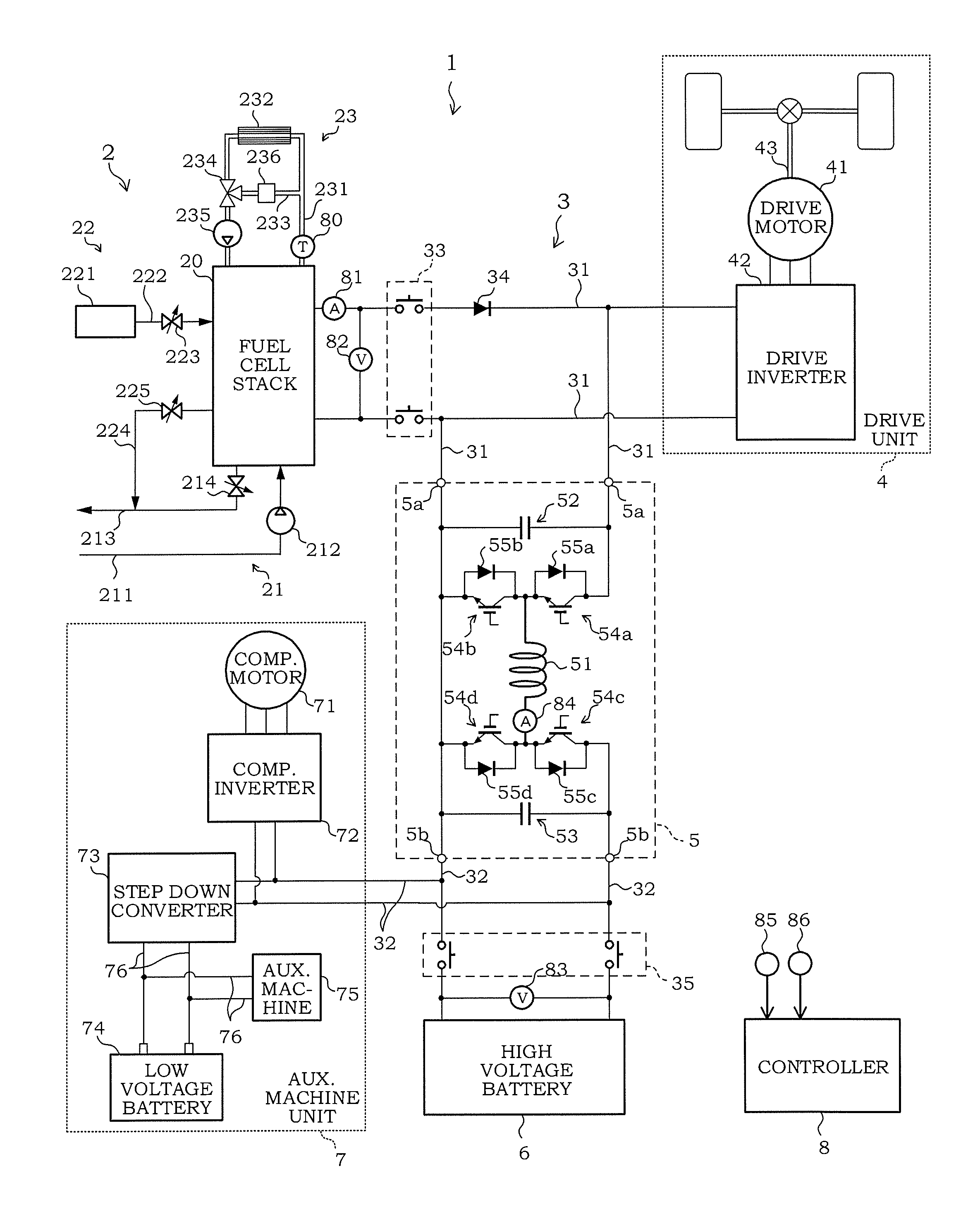
[0022]In a case where such a fuel cell is utilized as a power source for a vehicle, the electric power to be required becomes greater. For this reason, the fuel cells are used as a fuel cell stack in which several hundreds of the fuel cells are laminated. Then, by constituting a fuel cell system for supplying the anode gas and the cathode gas to the fu...

second embodiment

[0120]Next, the content of a control program according to a second embodiment of the present invention will be described. A control program according to the present embodiment is different from that according to the first embodiment with respect to the content of the generated electric power calculating unit 14. Hereinafter, its difference will be described mainly. It should be noted that components serving as the similar functions in the first embodiment described above are denoted by the same reference numerals, and the overlapping explanation will be omitted appropriately.

[0121]FIG. 7 is a block diagram for explaining details of the generated electric power calculating unit 14 of the control program according to the present embodiment.

[0122]In the first embodiment described above, the value obtained by multiplying the target output current previous value and the detected line voltage is used as the generated electric power.

[0123]On the contrary, in the present embodiment, a secon...


PUM

PropertyMeasurementUnit
electric poweraaaaaaaaaa
voltageaaaaaaaaaa
output currentaaaaaaaaaa

Abstract

A fuel cell system configured to generate an electric power by supplying an anode gas and a cathode gas to a fuel cell includes: a connection line configured to connect the fuel cell to an electric load; a converter connected to the connection line and a battery, the converter being configured to adjust a voltage of the connection line; a target output current calculating unit configured to calculate a target output current of the fuel cell in accordance with a load of the electric load; a converter control unit configured to carry out a switching control for the converter in accordance with the target output current; and a flow rate control unit configured to control a flow rate of the cathode gas to be supplied to the fuel cell in accordance with the target output current. The target output current calculating unit sets up an upper limit to the target output current on the basis of a generated electric power of the fuel cell and a guaranteed minimum voltage of the connection line for ensuring performance of the fuel cell and the electric load.

Description

TECHNICAL FIELD[0001]The present invention relates to a fuel cell system.BACKGROUND ART[0002]As a conventional fuel cell system, there is one in which a battery is connected in parallel to a connection line, which electrically connects a fuel cell to a drive motor via an inverter, via a step-up / down converter (see JP2010-257928A).SUMMARY OF THE INVENTION[0003]A fuel cell system under development now has a system configuration in which a fuel cell is connected to a drive motor via a connection line and a battery is connected to the connection line via a converter. In such a system configuration, an output voltage of the fuel cell is the same electrical potential as an applied voltage of the drive motor.[0004]Further, the fuel cell system also has a control configuration in which a target generated electric power of the fuel cell that is calculated on the basis of a state of an electric load, such as the drive motor and the like, is converted to a target output current according to an...

Claims


Application Information

Patent Timeline
Patent Type & Authority Applications(United States)
IPC IPC(8): H01M8/04537H01M8/04828H01M8/04746
CPCH02J3/387H01M8/04888H01M16/006H01M8/04589H01M8/04753Y02E60/50H01M8/0488H01M8/04619H01M2250/20B60L11/1881G01R31/3606G01R31/362G01R31/3658H01M8/04559G01R31/367G01R31/3835B60L58/12B60L50/72B60L58/40B60L58/32H02J2300/30H02J3/381Y02T10/70Y02T90/40Y02E60/10H02J3/46Y04S10/126Y02E60/00
Inventor MATSUMOTO, MICHIHIKO
Owner NISSAN MOTOR CO LTD
Why Eureka
Try Eureka