Inrush limiter for motor drive ac/ac power converters

Active Publication Date: 2016-09-15
HAMILTON SUNDSTRAND CORP
View PDF4 Cites 16 Cited by
  • Summary
  • Abstract
  • Description
  • Claims
  • Application Information

AI Technical Summary

Benefits of technology

[0042]One or more embodiments limit inrush current and its adverse effects on the components of the motor drive, but without the need for the pre-charge components described above for conventional systems, whilst still minimising current stress on the remaining components.
[0043]Such embodiments may achieve this by configuring t

Problems solved by technology

Such known rectifier/inverter drive systems are known to suffer from a high initial inrush current.
Start-up transients can be harmful to the system—significant switching transient may occur upon applying power to the rectifier.
Such inrush currents are surge currents and can cause components of the drive system to fail and/or may also create electromagnetic interference that could interfere with other equipment in the power system and lead to catastrophic failure.
Further, the additional circuitry adds additional complexity and cost to the drive system.
Also, the pre-charge circuitry components are only

Method used


Image

  • Inrush limiter for motor drive ac/ac power converters
  • Inrush limiter for motor drive ac/ac power converters
  • Inrush limiter for motor drive ac/ac power converters

Examples


Embodiment Construction

[0054]The preferred SCR uses a thyristor on the positive leg of each rectifier phase, which allows for the controlled commutation of each phase. The same effect may be achieved by using thyristors on the negative leg of each rectifier phase or by a fully controlled rectifier. With phase angle control of the SCR, the rectified voltage can be gradually increased over a defined period, thus controlling the DC link and AC line currents to a desired value, without surges.

[0055]The phase angle control algorithm can be implemented by FPGA, microprocessor or discreet devices.

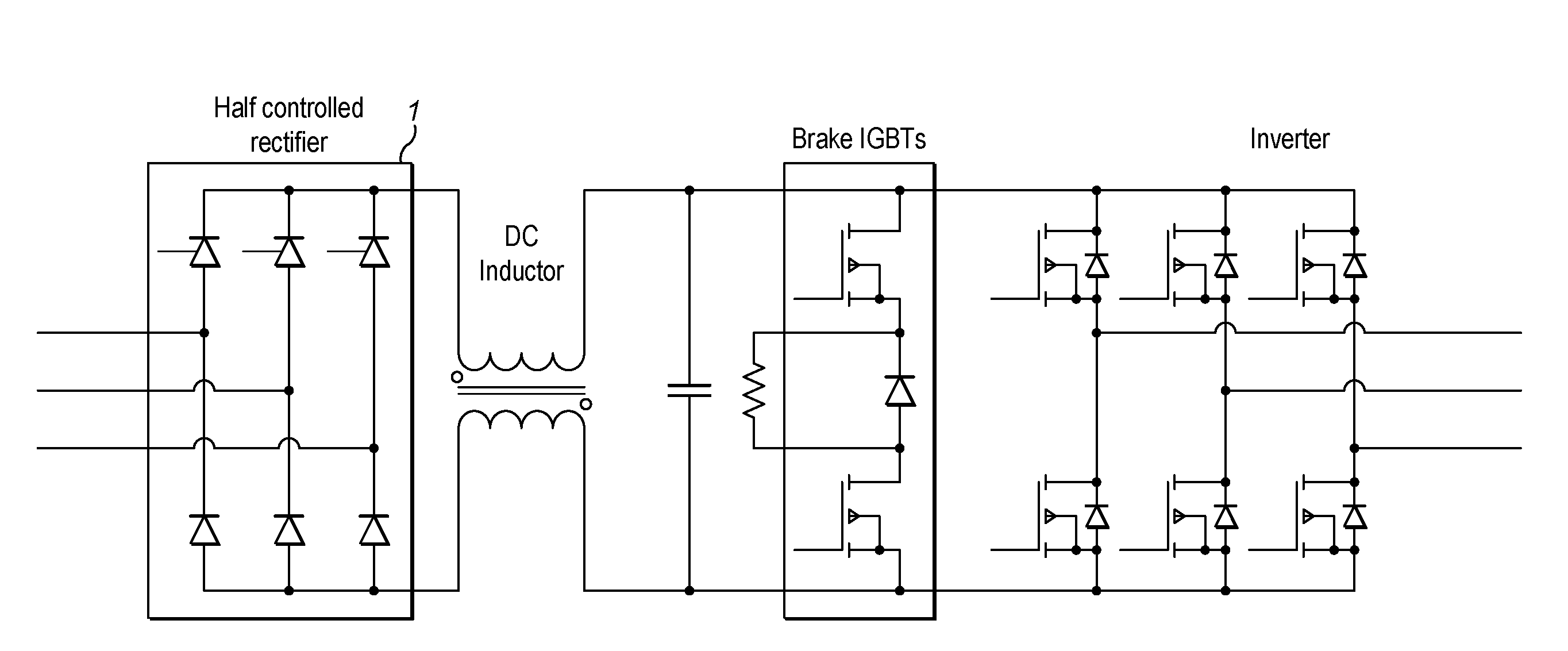
[0056]FIG. 5 shows the topology for a controlled rectifier according to the present invention. It can be seen that the series resistor and parallel thyristor of the existing system is no longer required, due to the use of a modified rectifier design—i.e. using a half-controlled rectifier.

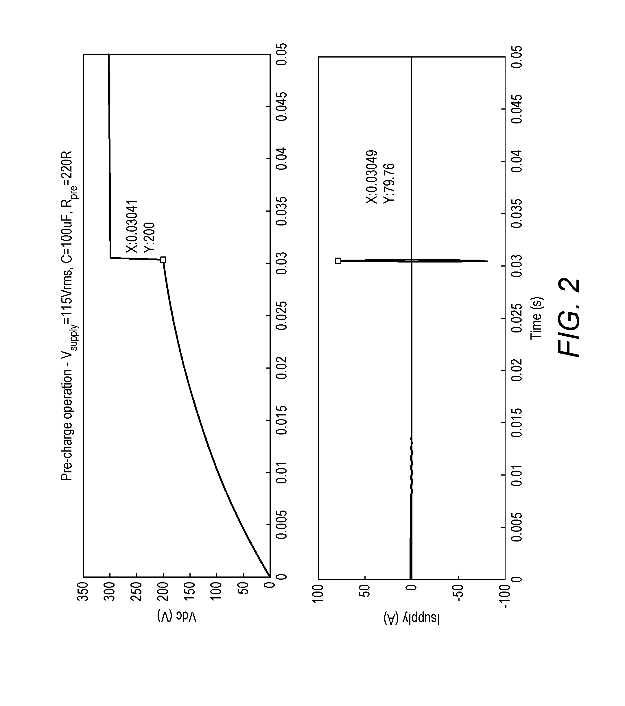
[0057]FIG. 6 shows a possible implementation, created using simulation software, of the invention, split into sections each relating t...


PUM


Abstract

A variable frequency motor drive system configured such that the dc link capacitor charge is increased gradually, thus avoiding the above-mentioned transients. In the most preferred embodiment, the present invention ensures a gradual increase in the rectified voltage by providing the rectifier as a half-controlled thyristor rectifier (SCR) in place of the standard diode rectifier.

Description

[0001]This application claims priority to Great Britain Patent Application No. 1504161.9 filed Mar. 12, 2015, the entire contents of which is incorporated herein by reference.TECHNICAL FIELD[0002]The present invention relates to variable frequency motor drives and, more particularly, circuitry for limiting the effects of inrush current in such motor drives.BACKGROUND OF THE INVENTION[0003]In recent times, advances in alternate current (AC) motor drives have allowed for an increased use in aerospace applications. The drives themselves have become more advanced, however the key to further successful integration of electrical motor drives in aerospace applications is increased power to weight, power to size and thermal performance.[0004]Such drives generally comprise a rectifier for rectifying the AC input to direct current (DC). The DC power is provided to an inverter which converts the DC voltage to AC to drive the motor with varying levels of voltage and current, according to contro...

Claims


Application Information

Patent Timeline
IPC IPC(8): H02P27/06H02M5/458
CPCH02M5/4585H02P27/06H02M1/36H02M1/0085H02M1/32H02M5/4505
Inventor BENN, ANDREW J.
Owner HAMILTON SUNDSTRAND CORP
Why Eureka
Try Eureka