Optical Phased Array Using Stacked Parallel Plate Wave Guides And Method Of Fabricating Arrays Of Stacked Parallel Plate Waveguides

Inactive Publication Date: 2016-09-22
BAE SYST INFORMATION & ELECTRONICS SYST INTERGRATION INC
View PDF1 Cites 3 Cited by
  • Summary
  • Abstract
  • Description
  • Claims
  • Application Information

AI Technical Summary

Benefits of technology

The patent text describes a waveguide structure that can control the direction of a laser beam using electric fields. The structure consists of multiple layers of dielectric material that are stacked and modulated with different voltages to deflect the output beam in a predictable way. The text also describes a method for fabricating these crystalline dielectric materials onto metal layers. The technical effects of this technology include improved precision and control over laser beam direction in applications such as optical communications and imaging.

Problems solved by technology

Current optical beam steering methods, most of which are based on simple mechanics, are too bulky, slow, or inaccurate.
Optical phase arrays for non-mechanical laser beam steering applications are difficult to fabricate without grating lobes because the devices require spacing of waveguide elements that are less than λ / 2.
Existing non-mechanical pointing solutions suffer from small field of regard (FOR) and / or are limited in wavelength to the visible or short wave infrared (SWIR) bands.
Existing mechanical pointing solutions suffer from large size, weight, and power requirements, low slew rates, high settle times, tight mechanical tolerances, and do not permit random access scanning.
It is difficult to build near-hemispherical field of view with regard to mechanical pointing systems without projecting into the air stream.
Thus, a heretofore unaddressed need exists in the industry to address the aforementioned deficiencies and inadequacies.

Method used


Image

  • Optical Phased Array Using Stacked Parallel Plate Wave Guides And Method Of Fabricating Arrays Of Stacked Parallel Plate Waveguides
  • Optical Phased Array Using Stacked Parallel Plate Wave Guides And Method Of Fabricating Arrays Of Stacked Parallel Plate Waveguides
  • Optical Phased Array Using Stacked Parallel Plate Wave Guides And Method Of Fabricating Arrays Of Stacked Parallel Plate Waveguides

Examples


Embodiment Construction

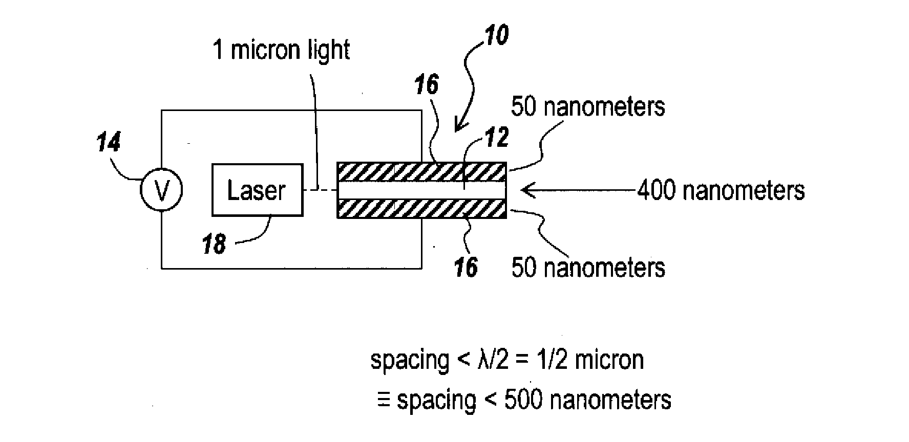
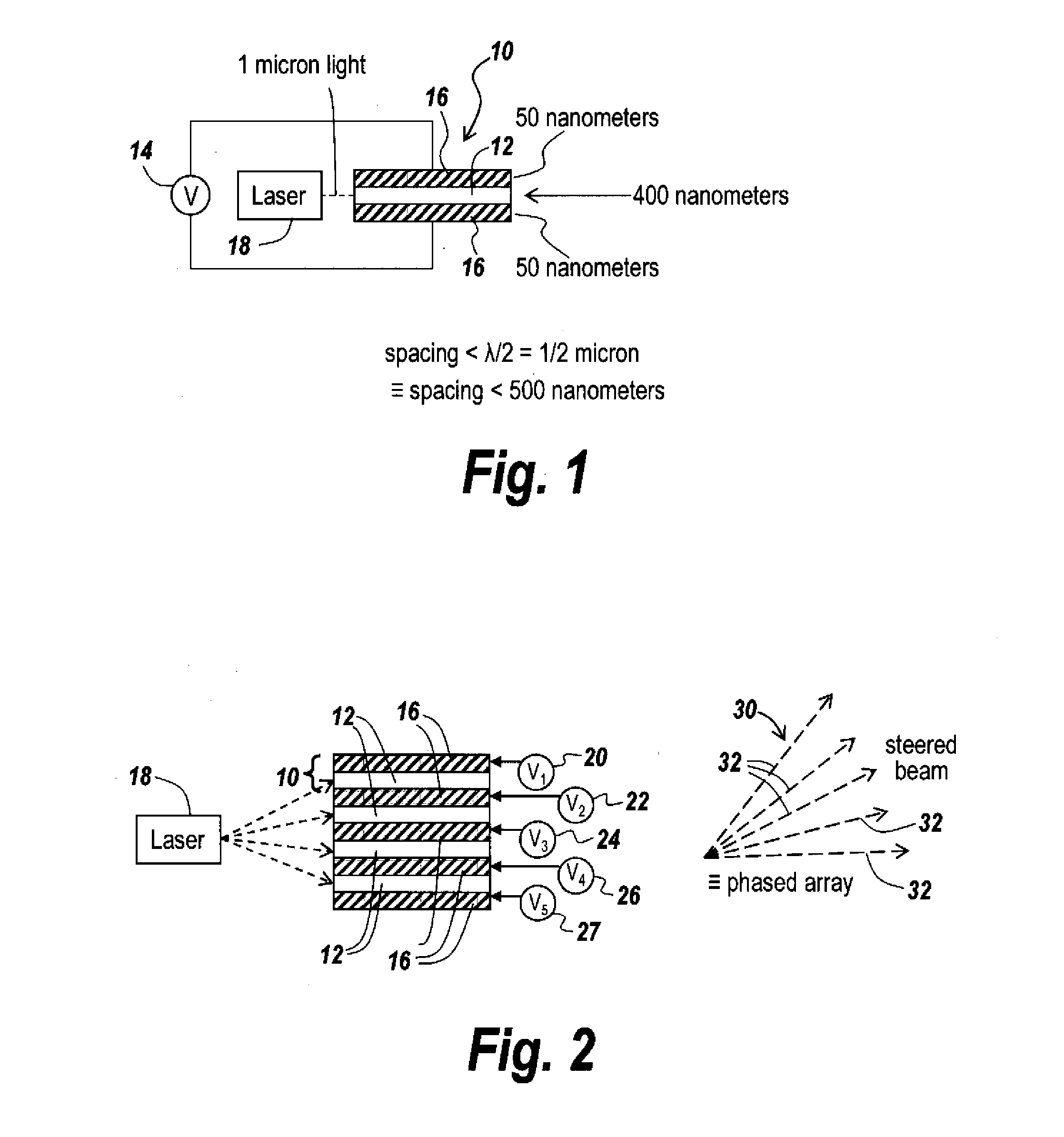
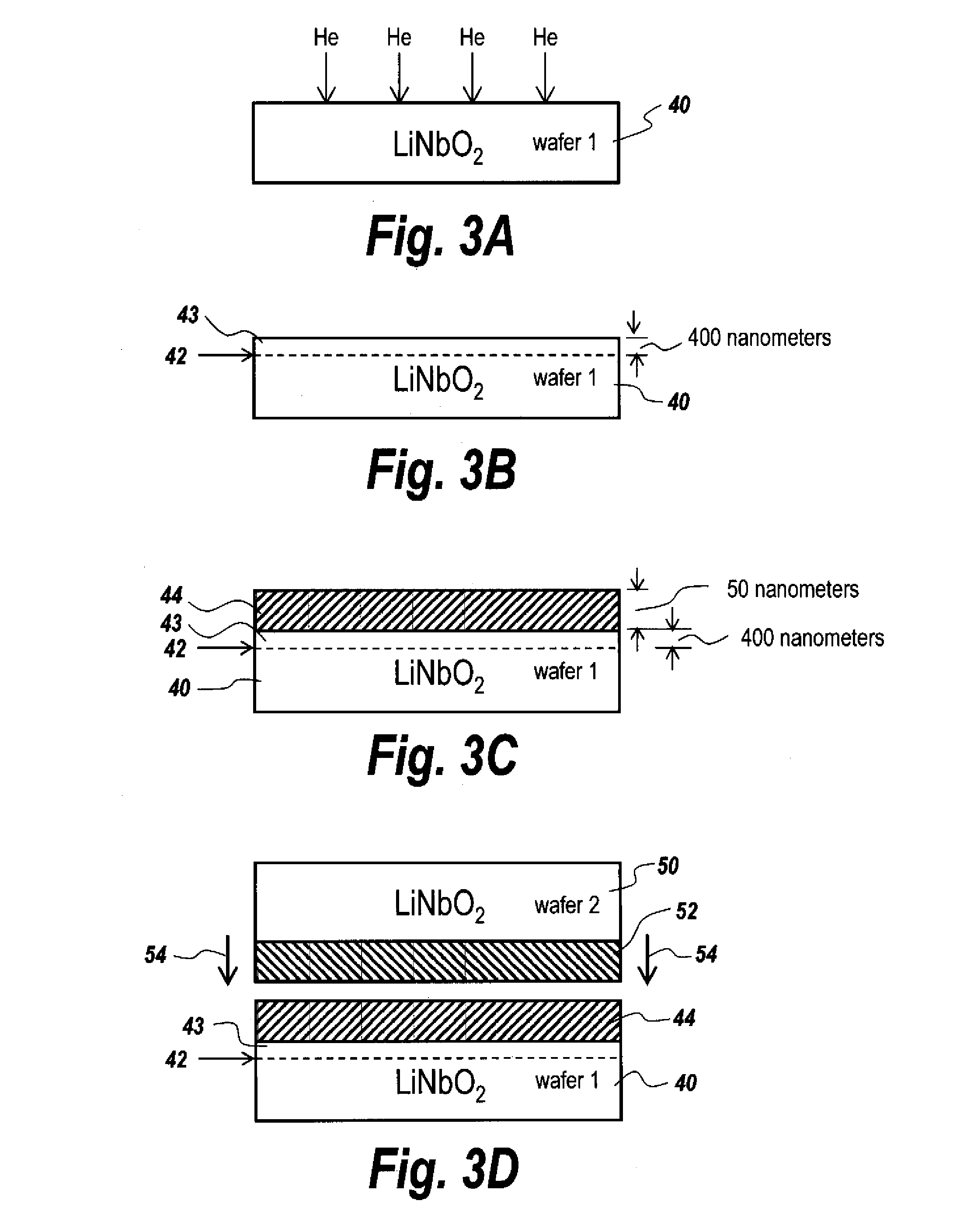
[0020]The subject invention is directed to a conformal optical beam steering array utilizing an optical phased array having a near hemispherical field of regard. A stacked waveguide structure is used in which parallel plate waveguides are required. Additionally, a method is provided for phasing the output of the waveguides so as to effectuate beam steering. The present invention operates by controlling the propagation constant (βz) in stacked parallel-plate waveguides, with the propagation constant controlled using the linear electro-optic effect. To control the propagation constant, voltages are applied across the dielectric material between the plates of the parallel plate waveguides, with the dielectric material being a birefringent material that is nearly transparent in the infrared range. In one embodiment, the dielectric material is lithium niobate.

[0021]It is desirable to have a laser system in which a solid state or fiber laser is directly coupled to a broadband conformal be...


PUM


Abstract

A method for fabricating crystalline dielectric material on top of metal layers to produce an apparatus for non-mechanical steering of an input laser beam is provided. The apparatus may include a plurality of stacked parallel dielectric waveguides, each waveguide of which is fabricated by separating layers of dielectric material from a donor wafer and bonding the separated layers of dielectric material to a receiving wafer. A plurality of voltages is applied across the stacked parallel dielectric waveguides. Each of the stacked parallel dielectric waveguides is electrically phase modulated to deflect an output beam in a predictable manner.

Description

CROSS REFERENCE TO RELATED APPLICATIONS[0001]This Application claims rights under 35 U.S.C. §119(e) from U.S. Application Ser. No. 62 / 047,266 filed Sep. 8, 2014, the contents of which are incorporated herein by reference.FIELD OF THE INVENTION[0002]This invention relates to lasers and more particularly, to non-mechanical laser beam steering.BACKGROUND OF THE INVENTION[0003]An Optical Phased Array (OPA) is the specific use of spatial light modulators to steer laser beams, or aim sensors, by progressive phase modulation. Coherent laser systems, including optical communication systems, LADAR imaging systems, and infrared countermeasure (IRCM) systems, require fast pointing systems that permit random access scanning of the battlespace in order to minimize timeline overhead to point at targets of interest. Conformal, wide-field-of-view beam steering is a significant enabler of IRCM, laser communications, and LIDAR applications on tactical fixed-wing and rotary wing aircraft.[0004]Current...

Claims


Application Information

Patent Timeline
IPC IPC(8): G02F1/295
CPCG02F1/2955G02B6/12G02B27/10G02F1/035G02F1/292G02F2201/30G02F2202/20
Inventor RUSSO, PETER N.JEW, JEFFERY L.MOFFITT, PAUL R.
Owner BAE SYST INFORMATION & ELECTRONICS SYST INTERGRATION INC
Why Eureka
Try Eureka