
Fast model predictive pulse pattern control

a pulse pattern and model technology, applied in the field of high-power electronics, can solve the problems of long initial time delay, long transient and harmonic excursion of currents, and the possibility of using optimized pulse patterns, and achieve the effects of low total harmonic distortion, fast elimination of large control errors, and high performan

Active Publication Date: 2016-09-22
ABB (SCHWEIZ) AG
View PDF4 Cites 9 Cited by
  • Summary
  • Abstract
  • Description
  • Claims
  • Application Information

AI Technical Summary

Benefits of technology

The patent describes a method for optimizing the performance of an electrical converter during both steady-state and dynamic operating conditions. The method ensures that the converter produces minimal harmonic distortion and matches industry standards for low current THDs and complies with grid code regulations. It also allows for fast torque and speed control of the controlled electrical machine and helps to quickly rejection grid voltage imbalances and control the active and reactive power of the system. This method can be applied in special purpose power converters used in industries such as steel mills and marine applications.

Problems solved by technology

Traditionally, it has only been possible to use optimized pulse patterns in a modulator driven by a very slow control loop.
This may lead to very long transients and to harmonic excursions of the currents when changing the operating point.
When a reference step is applied at the beginning of such a time interval, a significant amount of time may elapse before the controlled variables start to change, resulting in a long initial time delay and also prolonging the settling time.
Once the controlled variable has started to change, the transient response may be sluggish and significantly slower than when using deadbeat control or direct torque control, for example.
This may increase the risk that the flux vector is not moved along the shortest path from its current to its new desired position.
This may be equivalent to a large current, which may result in an over-current trip.
Related issues may also arise at quasi steady-state operating conditions, where small variations in the operating point and / or the inverter voltages occur.
Specifically, fluctuations in the DC-link voltage, resistive voltage drops in the machine's stator windings or in the grid impedance and transitions between different pulse patterns may lead to a degradation of the closed-loop performance of MP3C, if they are not properly accounted for.
Particularly in cases, where the optimized pulse patterns' switching transitions exhibit an uneven distribution in time and when a very low switching frequency is used, these flux errors may not be accounted for in a timely fashion due to the absence of suitable switching transitions.
As a result, large flux errors may arise that build up and persist over significant periods of time, leading to a poor tracking of the optimized pulse pattern's optimal flux trajectory.
This may impact the total harmonic distortion of the current in a detrimental way.

Method used


Image

  • Fast model predictive pulse pattern control
  • Fast model predictive pulse pattern control
  • Fast model predictive pulse pattern control

Examples


Embodiment Construction

[0018]It is an object of the invention to overcome the above-mentioned problems.

[0019]This object is achieved by the subject-matter of the independent claims. Further exemplary embodiments are evident from the dependent claims and the following description.

[0020]An aspect of the invention relates to a method for controlling an electrical converter. The electrical converter may be an inverter or an active rectifier. It may be an indirect or a direct converter. In particular, the converter may be a high power converter adapted for converting current with more than 100 A and / or 1000 V.

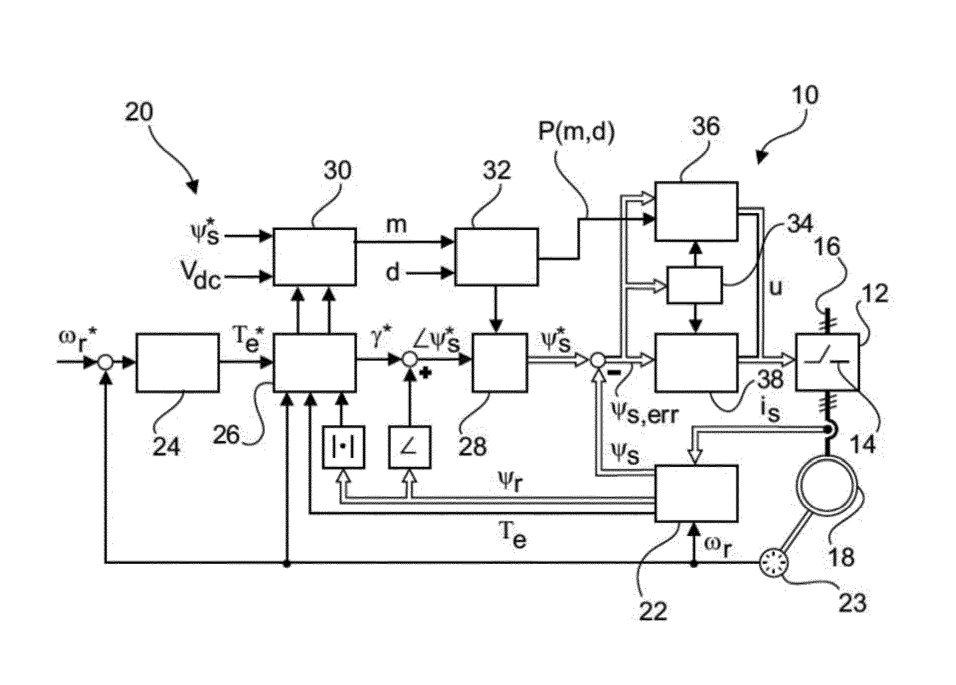
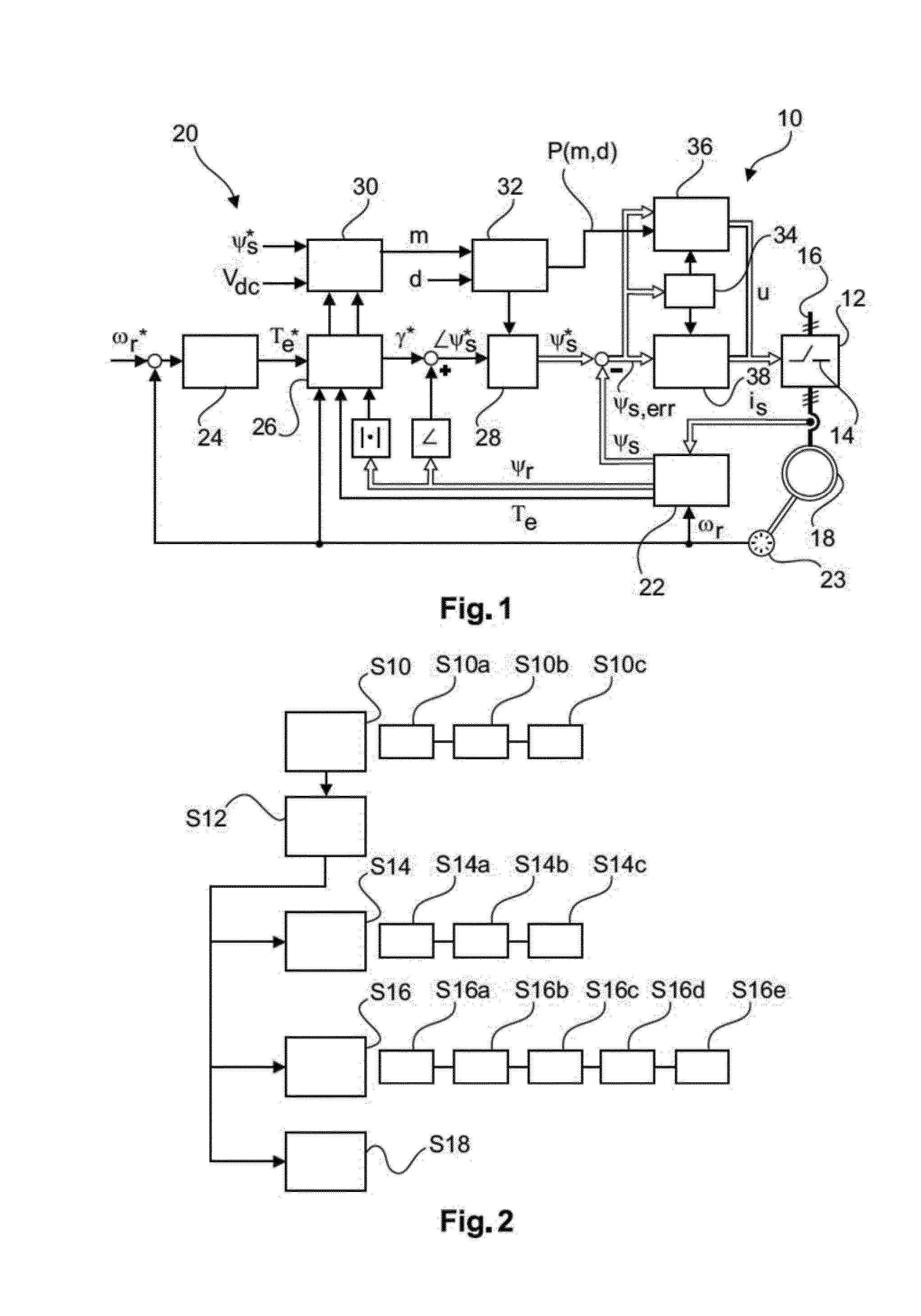
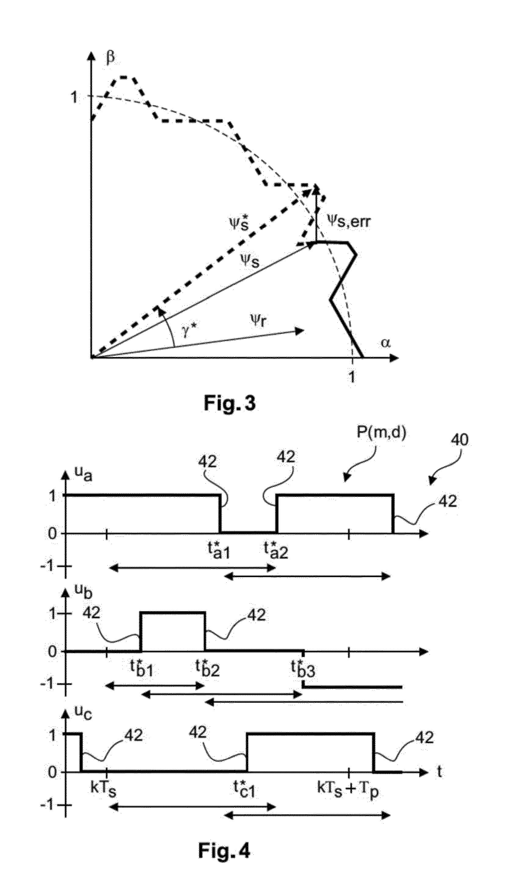
[0021]According to an embodiment of the invention, the method comprises the steps of: determining an error value based on a difference between an estimated output value and a reference output value, the estimated output value being based on measurements from the electrical converter; comparing the error value with an error band and in the case of the error value being within the error band, controlling th...


PUM


Abstract

A method for controlling an electrical converter comprises the acts of determining an error value based on a difference between an estimated output value and a reference output value, the estimated output value being based on measurements in the electrical converter; comparing the error value with an error band and in the case of the error value exceeds the error band, controlling the electrical converter by switching to a different control scheme. The converter is controlled with the modified pre-calculated switching by determining a pre-calculated switching sequence for the converter based on an actual state of the electrical converter, the switching sequence comprising a sequence of switching transitions of the converter; modifying the pre-calculated switching sequence by modifying transition times of switching transitions of the pre-calculated switching sequence, such that the error value is minimized; and applying at least a part of the modified switching sequence to the electrical converter.

Description

FIELD OF THE INVENTION[0001]The invention relates to the field of high power electronics. In particular, the invention relates to a method, a computer program, a computer-readable medium and a controller for controlling an electrical converter as well as to an electrical converter.BACKGROUND OF THE INVENTION[0002]Offline computed and optimized pulse patterns may be used for modulating the semiconductor switches in an electrical converter. Based on the actual speed and flux reference (provided for example by an outer control loop), a controller may determine a best suited offline computed pulse pattern, which is then applied to the semiconductor switches of the electrical converter. Offline computed optimized pulse patterns allow the minimization of the overall current distortion for a given switching frequency.[0003]When the electrical converter is used for driving an electrical machine, the current distortion is proportional to the harmonic losses in the stator winding of the elect...

Claims


Application Information

Patent Timeline
Patent Type & Authority Applications(United States)
IPC IPC(8): H02M1/08H02M7/04H02M7/44H02M1/12
CPCH02M1/08H02M7/44H02M7/04H02M1/12H02M7/539H03K5/08
Inventor GEYER, TOBIASOIKONOMOU, NIKOLAOSPAPAFOTIOU, GEORGIOS
Owner ABB (SCHWEIZ) AG
Learn More